
The basic two-transistor flasher shown below has found its way into dozens of applications due to its simplicity and versatility. Applications have included such diverse circuits as a micropower low battery indicator, a lightning detector, a off-line switching power supply, a micropower high voltage supply, an unusual beeping capacitance probe, a windshield wiper controller, a lamp dimmer, a police siren, and several others. The simple circuit can be used at very low frequencies, RF frequencies, low voltages, or even very high voltages with careful selection of transistors. The power handling capability and power consumption are also easily modified to suit the requirement.
This circuit is great for beginners! If you build it, it will flash. And you can easily change the on-time and flash rate.
The basic flasher is shown below. Notice that it is a "two-wire" circuit and simply connects in series with the load and battery. The two resistors on the base of the PNP set a threshold voltage and when power is applied the capacitor begins charging toward this voltage. When the capacitor voltage is high enough the two transistors begin to conduct. The current flow causes the voltage across the circuit to drop slightly and this drop causes a drop in the threshold voltage. The lower threshold voltage causes even more current and this positive feedback causes the circuit to rapidly turn on. It stays on until the capacitor discharges at which point a reverse process causes the circuit to suddenly switch off.
Power transistors may be added for handling higher current loads. The two circuits below are typical connections. In the first circuit a flasher circuit in series with a 220 ohm resistor turns on a power transistor. In the second circuit, a power FET is used in place of the NPN. A pull-down resistor is added to pull the gate low when the circuit turns off.
Don't hesitate to modify this basic circuit to meet your specific requirements. It is easy to troubleshoot and almost always works! Here are a few more ideas for the experimenter to try:
The circuit below is a "silent" metronome that keeps the beat without becoming a member of the band. The circuit flashes the 6 volt lamp at a rate set by the 20k potentiometer which can have a dial for setting the desired tempo. Alternately, the potentiometer could be replaced with a rotary switch and selected resistors. The lamp is an ordinary #47 bulb which will give good omni directional brightness but an LED and resistor could be used instead - try a 100 ohm in series with a high-intensity LED. The batteries could be three C or D cells for good life. This circuit could be used to generate "clicks" in a speaker but such metronomes are not particularly pleasing. The ambitious might replace the lamp with a solenoid which taps on the wall of a hardwood box or wooden chime for a "professional" sound.
Here is a low battery indicator that flashes a lamp when the battery voltage falls below about 5 volts. The circuit draws about 25 microamps when not flashing so battery life is not significantly shortened by the circuit. The two 1 megohm resistors set the switching point at V/2 (plus a little due to the emitter-base diode drop) and when this voltage is above the zener voltage the circuit cannot turn on. When the battery voltage drops below 5 volts, the base voltage drops to 2.5 volts and the emitter can reach a voltage sufficient to turn on the PNP (2N4403 or similar). When the PNP conducts, the NPN also conducts dropping the voltage across the circuit even more and the circuit snaps on. When the 4.7 uF capacitor has discharged, the circuit turns off and the capacitor begins charging again.
The zener is a "4.7 volt" type but in this circuit it is operating at a very low current and is limiting the emitter voltage to about 2.5 volts. Some experimentation may be necessary if another zener series is used.
The following circuit uses the flasher circuit to drive a complementary output stage and step-up audio transformer. This circuit is used in a high voltage breakdown tester but it would be useful for a variety of applications.
The transformer may be an audio type connected for step-up or step-down depending upon the desired output voltage. An old tube radio output transformer with the speaker winding connected to the circuit gave about 250 VRMS on the secondary and the voltage multiplier may be extended to reach thousands of volts DC.
Warning! This thing can produce lethal shocks when used to generate high voltages! Don't build it unless you are experienced and qualified to work with dangerous voltages.
Power transformers will also work but some experimentation may be necessary. The output transistors are shown as small-signal types but power transistors may be necessary if the load current is high. The duty cycle is not exactly 50/50 and other circuits would probably be better for high power inverters. This circuit is easily controlled, however. Pulling the 0.02 uF capacitor low is a good way to stop or reduce the output of the circuit. See the Geiger counter supply for an example that produces a regulated output voltage.
The AC out frequency at the secondary is several hundred Hz which may be changed by changing the 0.02 uF cap or the 6.8k resistor. The high frequency is useful for driving diode voltage multipliers as shown or D.C. rectifiers since smaller capacitors are needed then when using 50 or 60 Hz.
Here is a simple flasher circuit that uses no resistors! However, it relies on leakage in the base of the PNP germanium transistor and only some will work; be prepared to try a few. If you add a 100k resistor from the base to the collector of the PNP, the circuit will work with most germanium transistors and will work down to 1 VDC! The NPN should be a silicon type. The 100 uF may be replaced with a 22uF in series with a 5k resistor and it would be a good idea to add 39 ohms in series with the base of the NPN (but then the circuit starts to lose its charming simplicity).
Requiring a few more parts, this low voltage flasher uses ordinary silicon transistors and is powered by two cells. The circuit will work down to about 1.6 volts.
To flash a 600 mA bulb, change the 330k to 22k, the 100 ohm to 39 ohm, the 4.7k to 1k and the 4.7uF to 100uF.
Fig. 1 shows a versatile LED flasher circuit that works with smaller capacitor values. Note that this circuit is significantly different from the circuits above; the capacitor is in the base circuit. This configuration can give a long delay with much smaller capacitors than other flashers but the 2N4403 will not "saturate" so a few volts will remain across the circuit during the flash.
This flasher circuit is an excellent addition to the experimenter's bag of tricks because it offers a surprising level of performance for its simplicity. For example, increase the 1 megohm charging resistor up to 100 megohms (5, 22 megohms in series), increase the discharge resistor from 100k up to 1 megohm, and reduce the capacitor down to 0.01 uf and the circuit will flash an LED at about one flash per second. That's pretty slow for only 0.01uf. Increase the capacitor to 1uf (non-electrolytic) and the delay will reach 100 seconds. High gain transistors are best for this circuit and an MPSD-54 or similar PNP darlington is a great choice for the output transistor when driving higher current loads. Electrolytic capacitors may be used in this circuit but they often exhibit a little leakage so charging resistor values below 1 megohm are recommended.
A nice Christmas surprise can be constructed by building about five blinkers into a small, red felt stocking. Decorate the stocking with a glitter Christmas tree and poke the LEDs through holes in the stocking to light the tree. The battery can be dropped to the bottom of the stocking and held in place with a wad of paper. Glue a heavy piece of paper over the circuitry on the inside of the stocking to protect the wiring. The circuit will run for many days so it can be sent to Grandma and Grandpa with the battery installed and the lights twinkling.
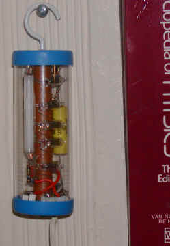 |
Here is a strange-looking flasher that uses an unusual form of the Marx high voltage multiplier. The traditional Marx multiplier uses spark gaps to repetitively charge capacitors from a high voltage supply (in parallel) then to suddenly connect them in series to generate a much higher voltage, near N times the supply voltage where N is the number of capacitors. This multiplier uses Lumex gas tube transient suppressors (GT-RLSA3230D) as the spark gap, providing reliable and repeatable triggering at about 250 volts (much lower than the typical spark gap). The 120 volt line voltage is rectified and doubled to provide enough voltage to trigger the suppressors and to reduce the required number of stages. The high voltage output builds up to just under 1000 volts when a miniature fluorescent tube fires. The tube firing discharges the output capacitor and the process begins again. The prototype is built into a clear plastic tube and hangs next to a bookshelf, looking pretty strange, flashing about every minute. |
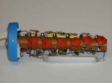
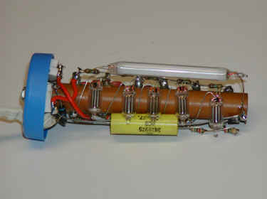
The circuit is constructed on a long phenolic tube with solder terminals installed on opposite sides but any construction technique will work. Remember that the circuit is line powered without any isolation so insulation is mandatory and the device should be plugged into a GFI protected outlet. Everything in an experimenter's lab should be on GFI circuits anyway!
As the large capacitor charges, the surge suppressors will dimly flicker with a blue light. In case you are wondering, ordinary neon lamps will also work but you will only get about 25 volts per bulb; it is hard to beat these suppressors. Notice that the Marx generator uses only one capacitor per stage instead of two as with the Cockcroft-Walton multiplier. Other values may be used in just about every case. Another prototype used .01 uF capacitors instead of 5000 pF, 100k instead of 1 meg and 1meg in place of the 3 meg so don't hesitate to experiment with what is on hand. This circuit can shock the begeebers out of you even when it is off so keepa your hands off!