
Also see:
Cockcroft-Walton Voltage Multipliers
These circuits generate high voltages and can cause dangerous shocks! Do not build these devices unless you are experienced and qualified to work on high voltage devices.
(Not for beginners!)
The following circuit is used to determine the breakdown voltage of electronic components without causing permanent damage. The circuit quickly ramps the high voltage up from zero and stops when the leakage current reaches a preset amount up to 100 uA. When power is applied the two-transistor flasher circuit drives the complimentary-symmetry output stage with a square pulse at about 3 or 4 kHz (set by the 0.02 uF capacitor). The output stage is connected to the speaker winding of an audio transformer from an old tube radio and the transformer steps the voltage up to about 250 VRMS . Many audio or power transformers will work here but a lower frequency may be better when using a power transformer. This high voltage AC is further stepped up using a diode voltage multiplier consisting of high voltage rectifiers and 1000 volt capacitors. The high voltage is filtered and current limited by two resistors and a 0.1 uF capacitor. This filtered voltage is connected to the positive test terminal. The negative test terminal receives the current that flows through the device being tested and converts it to a voltage with a 10 k resistor. 100 uA will give 1 volt. A zener is included to protect the op-amp. A reference voltage from 0 to 1 volt is applied to the other op-amp input to set the threshold current and when the D.U.T. current exceeds this current the 2N4401 turns on and steals current from the 0.02 uF capacitor in the flasher circuit, limiting the output voltage.
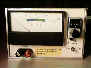
A voltmeter (not shown) is connected between the positive terminal and the circuit ground to read the voltage. (Note: Don't connect the meter to the negative terminal - the negative meter lead goes to ground.) A 40 megohm resistor (4, 10 megs in series) in series with a 50 uA current meter will make a 2000 volt full scale meter which should be adequate. The prototype shown in the picture also has a 200 volt scale which uses a 4 megohm series resistor. The power switch controls a relay which selects the meter range but this option is only slightly useful and the switching circuit must handle high voltage. If you wish to have meter ranges and you are using a current meter, connect the resistors to the high voltage and switch the other end of the resistors instead of running the high voltage directly to the switching device. Add neon lamps or other voltage limiting devices to ground to limit the voltage seen by the relay or switch.
Note: add a 10uF capacitor across the 9 volt zener.
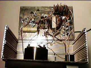
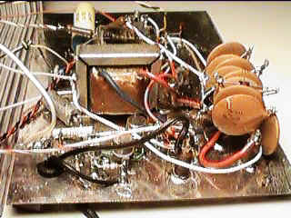
Construction is not critical except for the high voltage section which must be well insulated from the other circuitry. Notice the "air wiring" techinque for the voltage multiplier. Care was taken to ensure that no other wires were near the high voltage section.
To use the tester, connect the device to be tested across the test terminals, set the maximum current then turn on the power switch. Stay away from the terminals or you will get a nasty bite! After the breakdown voltage is determined, turn off the power and let the voltmeter discharge the capacitor before removing the D.U.T. (Device Under Test)
Try grading inexpensive 1N4001 or similar diodes. You will find breakdown voltages from 50 volts to over 1000 volts! The lower voltage devices can be used as zeners in very low current applications. Check the breakdown voltage of transistors. For example, connect the collector of a 2N4401 to plus and the emitter to minus and notice the breakdown voltage is below 100 volts. Now connect the base to the emitter and the breakdown voltage will go up. When you see breakdown voltage ratings like "Vceo", "ce" means "from collector to emitter" and the "o" means "with the base open".
![]()
Here is a simple circuit for generating over 100 volts from a 12 volt source for powering low current devices and experiments. The two transistors may be 2N4401 and 2N4403 or similar for lower power applications or higher power devices for heavier loads. If more power is desired then lower the two 10 ohm emitter resistors to 3.3 ohms. When driving power transistors, more drive may be achieved by adding two more gates and resistors in parallel with the two output gates shown. Notice that the two driver gates are simply in parallel with 220 ohm current limit resistors in series with their outputs.
The transformer is an ordinary power transformer but selecting a secondary voltage somewhat below the power supply voltage will give higher output voltage. The frequency is set near 60 Hz by the two 1 Meg. resistors and the 0.01 uF capacitor and this frequency may be varied for driving an audio transformer. The circuit will work well with other power supply voltages but do not exceed the voltage rating of the CMOS gates.
![]()