
This will be a collection of unusual ideas for somewhat difficult science fair projects - hopefully not a repeat of other sources.
Use colored LEDs and an old phototube to duplicate Millikan's
photoelectric experiment to calculate Planck's constant. Watch out, however;
most LEDs put out quite a broad spectrum even though they appear
monochromatic. You may need additional filters. There are pitfalls galore and discussing them would make for
a great write-up. Use a CMOS op-amp to hold the current in the tube near
zero by adjusting the voltage across the tube (simple feedback circuit).
Read the voltage as a function of light color striking the tube. One
possible schematic is fairly simple as seen below. Instead of using positive
and negative supplies, a dual, 5 V and 12 V supply is used; either approach
is fine. Both supply's' commons are connected to the circuit common (small
triangle ground symbols).


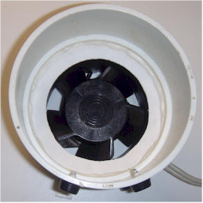
The photo shows a couple of typical phototubes, one plugged into a socket
with a banana plug adapter and partially inserted into a PVC plumbing "T"
painted black. My particular tubes have the pickup wire bent in a
rectangular shape, allowing maximum light to reach the cathode, but most
have a simple center wire as depicted in the schematic. They all suffer from
the problem of light hitting the wire, causing undesired emissions or a
"reverse current".
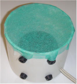
An LED holder made from more plumbing parts and an earphone
socket is at the top of the "T". The different colored LEDs are mounted in
earphone plugs that plug into the PVC adaptor. The left end of the "T" has a
removable plug that allows for inspection of the light hitting the tube. The
LEDs are powered by a variable power supply (not shown) and each has a 220
ohm resistor in series. The variable supply allows the brightness to be
varied. A current meter in series with the LED supply is a good idea; keep
the current below 30 mA.
Filters may be added over each LED to purify the spectrum. Unfortunately,
effective filters can be expensive! But, it turns out that colored
cellophane can make a big difference. (Packs of colored sheets of cellophane
are sold for arts and crafts projects.) Use a few layers of red cellophane
for the red and yellow LED (the yellow cellophane doesn't seem to attenuate
other colors much). Use a couple of layers of blue for an ultra-violet LED.
Adjust the light intensity for the maximum reading, too. The other spectral
components will get through but by dimming the LED, the reading will be
controlled by the dominant spectral line. Here are some quick test
results with and without cellophane filters:
| Color | Red | Yellow | Green | Blue | Ultra-violet |
| With Filter | 0.19 V | 0.65 V | 0.7 V | -0.26 V | 1.6 V |
| No Filter | 0.27 V | 0.27 V | 0.21 V | -0.13 V | 0.95 V |
There are some surprises in the data. For one, the voltages are low, but
the actual behavior of one of these phototubes isn't ideal. A major
undesired effect is most pronounced with the blue light. Notice the
voltage is negative! Apparently the little collector wire in the
tube emits more electrons than the target cathode at this particular
color. At other colors, the wire also emits electrons and this reverse
current lowers the voltage readings. The reverse current also lowers the
impedance of the tube which is handy; no high-value resistor is needed
in the circuit. When the tube is illuminated sufficiently, its impedance
drops fairly low. The op-amp is really setting a voltage that balances
the forward and reverse currents. Despite the shortcomings of this
particular tube, the trend that a higher retarding voltage is needed for
a shorter wavelength can be seen, especially with the cellophane
filters.

The photo above shows a typical test setup. You can see the LED power supply, the meter, different colored LEDs in earphone plug housings, bits of colored cellophane, the phototube housing and the electronics box. The box was made such that it can be used for a variety of projects. The power is supplied by a dual voltage molded supply (not shown) and comes in via the black cable. A panel lamp indicates power but the leads are plugged into the breadboard so that the light may be used for other purposes in the future. A dual banana jack on each end is used for external connections. A solderless breadboard is permanently fastened to the inside lid (see earlier photo). The breadboard is pushed to one side to allow for the addition of switches or other controls on the top in the future. This is a great way to build special projects that might have a limited useful life!

One word of caution! Those breadboards are insulated on the bottom by
paper and they can exhibit a tiny amount of leakage between pins. Bend
pin 2 of the op-amp up into the air and connect the tube (black wire
from banana plug in my case) and capacitor directly to the op-amp leg
with solder.
The prototype case is sitting on an aluminum sheet with a grounding clip connecting the two. This ground plane helps reduce line voltage related interference. It might be a good idea to connect an aluminum cake pan to the ground and lay it over the whole affair when making measurements. The pan will also help block ambient light. I wrapped electrical tape around the base of the tube so that the plumbing pipe fits snugly.
It doesn't really matter which way the tube is connected; the meter voltage will simply reverse polarity.
Search the Internet for "Einstein, Millikan and the Photoelectric Effect" by Richard Keesing. His excellent and interesting paper describes many of the problems with the experiment and would make an excellent reference for a science fair project. You won't be able to measure Planck's Constant to any degree of accuracy with this setup and his paper will explain why.


Design and build an "infrasound" microphone capable of detecting
frequencies below 20 Hz. The transducer could be a electret microphone with
unusually low frequency response. A couple of web articles recommend the
Panasonic WM-034BY for its unusually low frequency response. There
are several interesting articles on the web regarding possible designs. Interpreting the
data using FFT freeware. Maybe playing the data back speeded up to bring the
frequencies into hearing range would be interesting. This is not a particularly easy
project! An interesting "far infrasound" microphone may be had by simply
amplifying the output of a pressure transducer like the Motorola MPX100A
(see
https://www.techlib.com/electronics/barometer.html#Electronic%20Barometer).
If you want to try something a bit more difficult, consider making one of
these:

This could be called a "cansformer", I suppose. This low-frequency
transducer boosts the pressure wave that a small microphone element sees to
give much more sensitivity, especially to low frequency audio. This large
cookie tin has a soft plastic diaphragm stretched across the open end with a
circular piece of steel sheet cut from the bottom of a peanut can glued to
the center to act as a stiffener. The red cookie tin lid has a hole cut in
the center to let in the sound. The metal stiffener will move up and down
with low-frequency sound waves by an amount that is proportional to the can
height (ignoring the stiffness of the diaphragm). By connecting the center
of the diaphragm to the center of a smaller diaphragm on a much shorter can,
the pressure changes in the smaller can will be a multiple of the pressure
changes in the larger can. If the smaller diaphragm moves the same distance
as the larger one (and it will if they're mechanically connected), that distance will result in more pressure change since
it is a higher percentage of the total height of the can. The larger surface
area of the bigger diaphragm provides the extra force needed to move the
smaller diaphragm against the higher pressure. This pressure transformation
gives more output for a given audio volume and, therefore, better
signal-to-noise performance without resorting to banks of microphones.

The photo above shows the diaphragm peeled back, revealing the smaller mint
tin mounted on a strip of wood. (The little microphone off to the side is
only there for comparison purposes.) The mint tin also has a diaphragm made
from the same soft plastic material (scavenged from a zipper bag for a
comforter). Soft rubber would also work (perhaps from a toy tom-tom drum).
The smaller diaphragm has a smaller disk cut from another peanut can and the
lid of the mint can has a fairly large hole. The metal disks are glued into
place facing each other and the mint can support is positioned so that a
small, powerful magnet bridges the gap when the large diaphragm is in place.
Lay a straightedge across the mouth of the big can to help position the
support. The top of the magnet should just touch the straightedge. The
magnet mechanically connects the two metal disks and makes it easier to
assemble and disassemble the unit. Make sure the disks are made from a
magnetic material. Forcing the lids over the plastic stretches the plastic
nicely, leaving a smooth, tight diaphragm.
A small hole is drilled into the bottom of the mint can and an electret
microphone is mounted over the hole with epoxy such that the microphone hole
is exposed to the inside of the can:

My idea was that the microphone must have some sort of internal, precision
pinhole to allow the pressure to slowly equalize across the electret
element. This slow leak will relieve pressure differences and keep the mint
can at ambient pressure. The leak needs to be slow so as not to attenuate
low-frequency response. Now the leak also balances the pressure in the much
larger volume of the small can so the time constant must be very long. Once the epoxy cures, the diaphragm is stretched
over the can and the lid is squeezed on, stretching the diaphragm to a nice,
unwrinkled state. If the hole in the mint lid is big enough, the steel disk may be
glued into position after the diaphragm is stretched. A little glue was
applied to the underside of the edge of the diaphragm before assembly to
help make a good seal.
The larger can could probably stand to have a pressure relief hole, too. But
it can be difficult to make a leak that isn't too fast so some
experimentation may be required. The prototype happened to have a slow leak so no hole
was needed. Pressing in the big diaphragm and then releasing it after a
minute results in a slow return to the flat position, perhaps taking 30
seconds. The motion of the large diaphragm can be hard to see, so
temporarily glue a pointer stick to the diaphragm and let it rest on the lip
of the hole. Slight changes in the height of the diaphragm will cause the
end of the stick to move up and down against a scale.
The gain of the prototype is only about five which is lower than expected.
The lower gain is probably due to the attenuation caused by the stiffness of
the diaphragms, especially the smaller one, and possibly the relative
diameters of the cans. The gain and sensitivity were checked by positioning
the transducer in front of a large speaker driven by a signal generator set
to 15 Hz. The second microphone glued to the wooden support gives a much
smaller signal than the one mounted to the mint can, perhaps by a factor of
five or
six.
Make sure to seal the connector for the microphone cable. I used potting wax
on the inside of the connector but epoxy would also work.
Most sound cards only go down to about 20 Hz so another type of input may be
desired. One possibility I am considering is to use the amplified and
low-pass filtered microphone signal to drive a voltage to frequency
converter with a center frequency well above the frequency to be monitored,
perhaps 2 kHz. The audio will FM modulate the 2 kHz and FFT software can see
the variation as sidebands around the center frequency.
Also see Infrasound.


An ordinary computer fan draws air through a piece of dust cloth and highly radioactive radon "daughters" accumulate on the paper. The radiation will last for about two hours after the fan is turned off. This filter was used in a controversial experiment that shows how one might use the collector in an experiment. I would recommend another theorem since suggesting something positive about second hand smoke might not be popular among judges! Long-term variations in radon levels might be a good project. Can radon daughters be swept up with charged plates or plastic electrets? How quickly does radon build up in a sealed camper's tent? How about a dirt-floor storage shed or barn? Can you pick up radon variations as a function of earth tremors, thunder, barometric pressure change, etc.?
Also see Radon Detector for the Student.