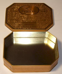
First I looked around for a suitable can and found a nice Godiva chocolate tin:
I'm off to drill holes, etc. (Fri. 7:44 pm)
I just sanded the finish off the lip of the can and inside the lid where the lip touches. Hopefully this will provide adequate grounding.
O.K., one hour and I have this box:
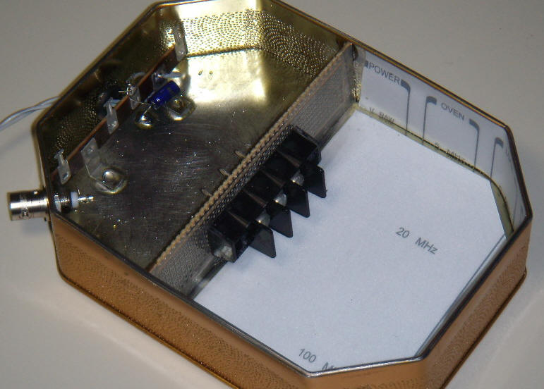
One side is insulated with pieces of Lexan from some old instrument labels and that is where the diode will go. There is a three-terminal feedthru to the amplifier side supported by a piece of perf board. The amplifier side has a BNC for the signal and a terminal strip for power connections. I just added a 47uF to ground on one terminal for the positive power supply voltage.
Now the thinking part. I need coffee. Coffee Break! Be back in a few. It's 8:44 now.
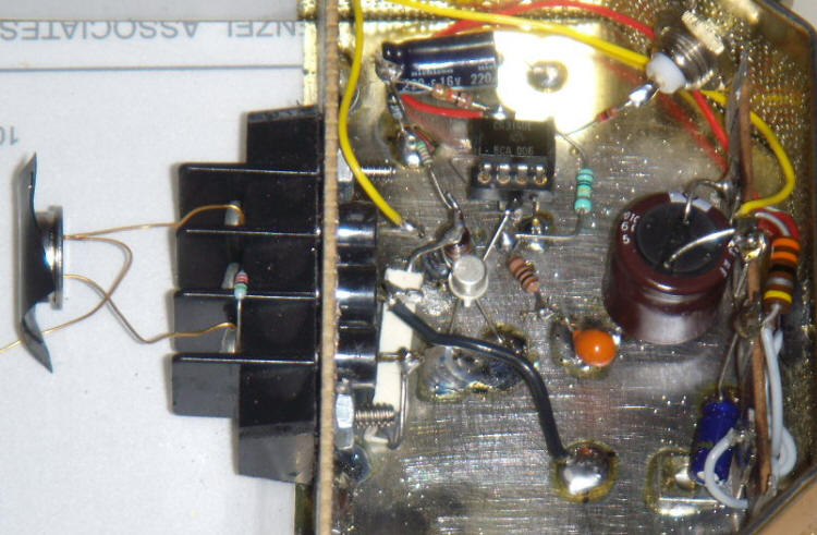
I'm back and working on an amplifier ckt...done:
I'll sketch the schematic now...

I used one of the metal can electrometer JFETs that I have in quantity. These have pretty low IDSS, typically below 100uA so I just grounded the source and selected a resistor on the drain to give about 5 volts out of the op-amp. The value turned out to be 51k. I biased the JFET with a huge 13 gigohm resistor in case I want to try really high impedance experiments. The PIN diode needs a fairly low resistor to ground to handle the leakage current, in this case 22 megohm and that resistor sets the input impedance. The 470 pF porcelain capacitor (big white block below black connector pins) is very low leakage and big enough for anything I might want to try short of DC. In a radiation detector circuit, both resistors could be 22 megohms and the capacitor could be an ordinary ceramic type. The drain has a zener diode lightly biased and bypassed by a large capacitor to prevent feedback via the power supply rail and to reduce the susceptibility to power supply noise. The CA3140 isn't critical; I just like them. I DC-coupled the output so that I can see what the amplifier is doing simply by looking at the DC level which should be near 5 volts.
I turned it on and immediately started getting >1 volt pulses from the geiger counter calibration disk.
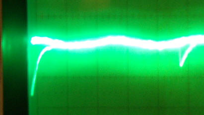
I caught one with my camera, no easy feat. It looks like about 2 volts (1V/div). There's a little one, too. These are the only two sizes that are commonly seen with that disk. A lantern mantle gives two different sized pulses, one about 1 volt and the other about 1.7 volts.
I was only patient enough to see two pulses from the uranium marbles, one at about .5 volts and the other was "big", maybe 2 volts. This is no geiger counter! I still maintain that the area is too small to compete with a large ion chamber or even a tiny geiger tube. I just had to wait a full minute to see a single background pulse. The target is just too small.
I just added a huge (6,800 uF) capacitor from the power pin to ground where the power enters the diode chamber (top black pin with the yellow wire) and the hum completely went away.
This is a neat test chamber!