
I can't function without this thing!
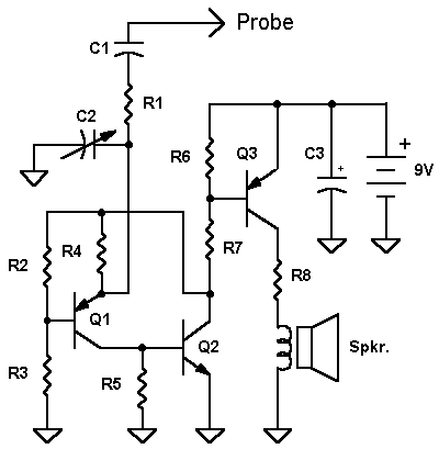
The Curious C-Beeper uses the two-transistor flasher in conjunction with a darlington transistor to make a most unusual capacitance beeper probe. When a capacitor is touched to the probe, the probe beeps at a frequency that varies with capacitance. The frequency change is so steep with capacitance that tiny capacitors may be precisely matched or an exact fixed value may be selected to replace a trimmer in a prototype. If the user has reasonably moist skin, simply holding one lead of the capacitor to be tested while touching the other lead to the probe is all that is necessary. The user's body forms the other connection through the beeper's metal case. When the beeper is properly adjusted it draws only 10 uA with nothing touching the probe - no power switch is required. This design is optimized for capacitors less than about 0.1 uF (100 nF). Large capacitors give a low frequency "clicking" sound and small capacitors sound a tone that increases as the capacitance decreases. Many decades of frequency change occur over the beeper's range giving even the more tone-deaf among us sufficient change to discern slight differences in capacitance.
 |
|
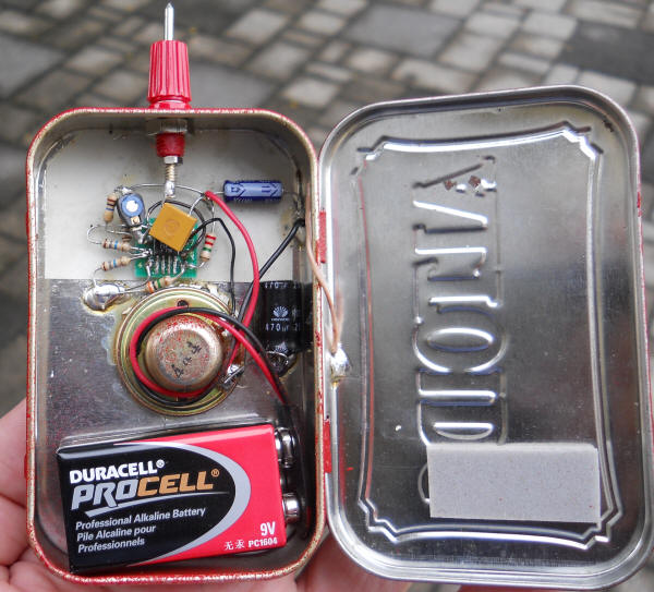
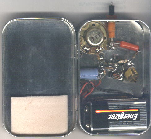
The probe should be built into a metal box so that one hand makes good contact to the circuit ground. My beeper is built into an Altoids Mint box with the paint sanded off (use steel wool). Leave the paint if you like the artwork! I prefer the scientific motif. The open beeper is shown below. The thin metal box is easily soldered so all ground connections are directly soldered to the box. Also note the strip of PCB material soldered into place next to the battery to form a simple battery holder. A strip of foam pushes on the battery when the lid is closed. There is a single small hole for the sound under the speaker.
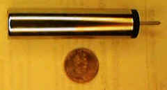
Below is a fancy version built into a round nickel-plated can using a miniature 7.5 volt battery and a small electro-magnetic transducer from an old processor card (the "beeper" speaker). The left end of the probe has a small hole for the sound and the probe end has a tight-fitting grommet with a probe tip in the center hole. A ground connection is made internally.
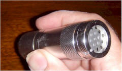
Those $3 LED flashlights also make for a nice package, plus you get a handful of bright LEDs:
Parts substitution is risky! The resistor values are selected to barely turn on the transistors to conserve battery power. The transistors must have very high gain and good low current properties. The MPS-A18 is a very high gain transistor with excellent gain at very low currents and substitutions may not work well. The capacitors are not particularly critical but the trimmer might require a little care. The trimmer is adjusted until the beeping just stops and only a very weak squeal is heard when a 2.2 pF capacitor is touched to the probe. Attempting more sensitivity risks excessive battery current. Less sensitivity is fine if the probe is not to be used on very low values.
The Curious C-Beeper will become indispensable in virtually no time!
|
Quickly match capacitors and trimmers. Forget the capacitance meter when matching parts from the parts bin or selecting a fixed value to replace a trimmer - the "fingers as conductors" feature makes the C-Beeper super-fast when searching for that perfect value. | |
|
Easily detect tiny variations when a capacitor is heated or cooled to quickly discriminate between NPOs and "Stable" dielectrics. General purpose and temperature compensating dielectric are quite easy to spot. | |
|
The C-Beeper makes an excellent cable fault locator - the end with the open will have less capacitance and beep at a much higher pitch or not at all. A break along an unshielded bundle can be spotted by grabbing the bundle at various points while listening for the capacitance change. | |
|
Identify which wire is which at the end of a bundle without stripping back the insulation. Touch the bare wire at one end with the C-beeper probe and pinch the still-insulated wires at the opposite end. The right wire will drop the pitch. | |
|
Identify traces on unpopulated PCBs right through solder mask - touch the C-beeper to the exposed end of the trace and use a finger to follow the trace across the board. | |
|
Check the value of feedthrough capacitors after they are installed - a difficult operation with a capacitance meter. | |
|
Identify varicap diodes. They beep at a much lower pitch than regular diodes. | |
| Make a small flat plate electrode and line voltage electric fields may be detected.
Follow wires behind walls and ceilings or determine if wires are "hot" without
touching them. The C-Beeper's tone is modulated by the AC voltage causing a warbling
sound. Circuits with lamp dimmers, solid-state switches or fluorescent bulbs are
especially easy to detect due to the harmonics on the line.
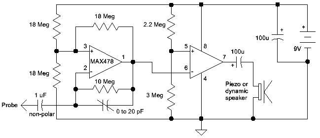
Curious C-Beeper Mark IIHere's an experimental version employing a micro-power op-amp. This is an "as-built" schematic and the values may be changed to some degree:
| |
|
The three 18 megohm resistors may be 22 megohm. | |
|
The 3 megohm may be 3.3 megohm; just make sure pin 5 voltage is a little on the high side of V/2. A little offset keeps the second op-amp off until a capacitor is tested. | |
|
The feedback resistor between pins 1 and 2 may be a lower value to achieve a higher pitch but the lower it is, the more conductive the user's hand must be; 3.3 megohm is probably as low as one should go. As you reduce the resistance you will also need to reduce the trimmer until it reaches zero capacitance. At that point remove the trimmer and consider adding a small trimmer to ground at the input and adjust until the beeping just stops. | |
|
The input cap should be a non-polar ceramic or film type and a smaller value is fine since this beeper is most useful for lower value caps. It really just clicks for values above 10 nF. I think a 0.1 uF is fine for most purposes. | |
|
My version relies on the low output current capability of the MAX478 (about 7 mA) to limit current into a 30 ohm headphone speaker. If your micro-power op-amp can supply significantly more current, add a resistor in series, say 100 ohms. Or use a piezo type speaker. Those little "beepers" on computer boards also work well (the ones without a built-in oscillator). The 100 uF in the output is "overkill" and a 10 uF should work for most speakers. I actually used 470 uF simply because it was laying on the bench. Piezo speakers don't need a cap at all. | |
|
The 0-20 pF trimmer capacitor should be the type that can go very low in value, just a couple of pF. Too much capacitance here and the probe won't beep for the lower value capacitors. The trimmer is adjusted until the beeping stops with nothing touching the probe then turned a little more in that same direction. When it's set right the beeper should not beep for capacitors below about 3.3 pF. Otherwise, it might start beeping with no capacitor and run down the battery. I was able to adjust mine to beep with a 1 pF but leaving it that way seems like asking for trouble (in the form of a dead battery). The op-amp approach is more stable than the transistor version so I'm not really sure how low a setting is practical. | |
|
The MAX478 is obsolete so choose a very low current op-amp as a substitute; The TLC27L2 looks like a good candidate. Make sure the op-amp can operate on 9 volts. If you don't choose a micro-power op-amp you will need to add a power switch. The prototype draws about 25 uA when not "beeping" so the battery should last a couple of years. |
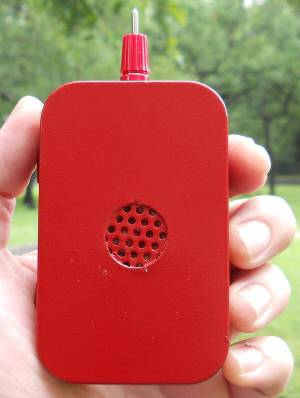
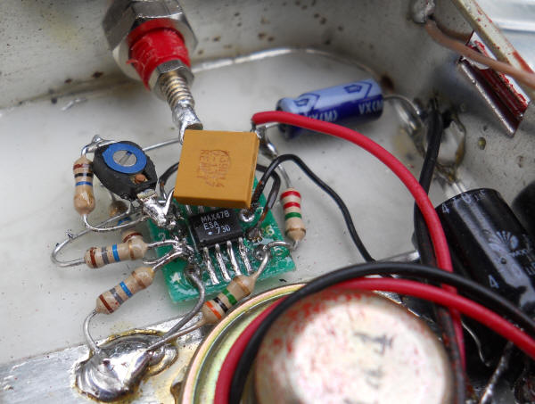
I built this version into an Altoids mint tin also. I decided to paint the tin but that insulates the metal. If you do the same, scrape the paint off the rolled lip of the lid such that the fingers make direct contact with the metal when holding the tin. Note the wire that connects the lid to the case. Construction isn't particularly critical but keep the probe wiring short. The capacitor goes directly from the probe to pin 2 of the op-amp.
