
Some of the projects in Area 50 aren't documented fully and this will be the extreme case. This device generates 4 and 5 MHz with little IMD between them for testing receivers or antenna amplifiers. The user applies the test signals and measures the amount of 1 MHz that is created by the D.U.T.
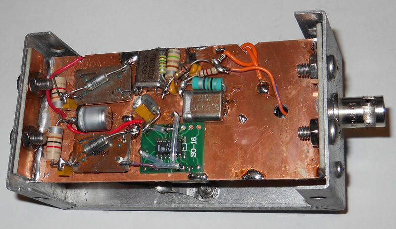
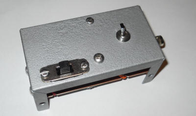
This project is intended for the experienced RF person and is presented here simply to trigger ideas. You should be able to zoom in on the image but build it your own way. Two clock oscillator signals at 4 and 5 MHz (10 MHz divided by two in my case) are passed through 4 and 5 MHz crystals to prevent the signal from one from getting into the other, thus preventing IMD. The power to each clock oscillator is filtered with 1 mH chokes, 0.1 uF and 1 uF caps to ground and a single 100 uF across the power from the battery. The output pin from each clock oscillator (or divider) drives one leg of the crystal and the other leg of the crystal has a parallel tank to ground consisting of a 1.5 uH (4 MHz) or a 1 uH (5 MHz) and selected capacitors to achieve resonance (maximum output). The two tanks are connected together via two 1k resistors and that node leads to the BNC. A 20 ohm resistor may be switched in to ground to reduce the output from -15 dBm to -25 dBm.


I can"t seen any 1 MHz generated internally so it's ready to use. By the way, you will need a low-pass filter just above 1 MHz to keep the two tones out of your spectrum analyzer or selective level meter or you will just be looking at that instrument's IMD.
The main idea is using crystals to keep the signal from one oscillator out of the other. If you try to do this with tuned circuits crosstalk becomes a serious problem. Each tank will need to be completely shielded. Crystals avoid the problem and allow for construction without any shielding to speak of.
Note how I made mounting brackets for the ground plane. Before mounting any panel components, drop your copper clad board into the case and use the sides of the case to hold the little vertical boards at the right angle. Solder in a few spots, remove the assembly and complete the beads of solder. I'd drill the holes in the case then use those holes to mark where to drill the mounting brackets with the board supported at the desired height. This technique can give you two sides for circuitry right in the middle of the case.
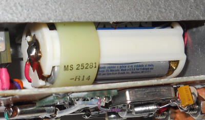
Also note that the 4.5 volt battery pack is from a cheap
flashlight and is held in place by a single nylon cable clamp. I'll be using
that trick in the future.