![]()
(Also see magnetic antenna version , op-amp version and Compound Transistor version)
Also: Original Lightning Detector Page
To observe the lightning strikes on a map in near real time try: https://www.iweathernet.com/lightning/latest-lightning-strikes-on-google-maps
The latency is usually under 10 seconds but that's long enough to make correlation with a flash from your detector with a flash on the map a bit challenging.
![]()
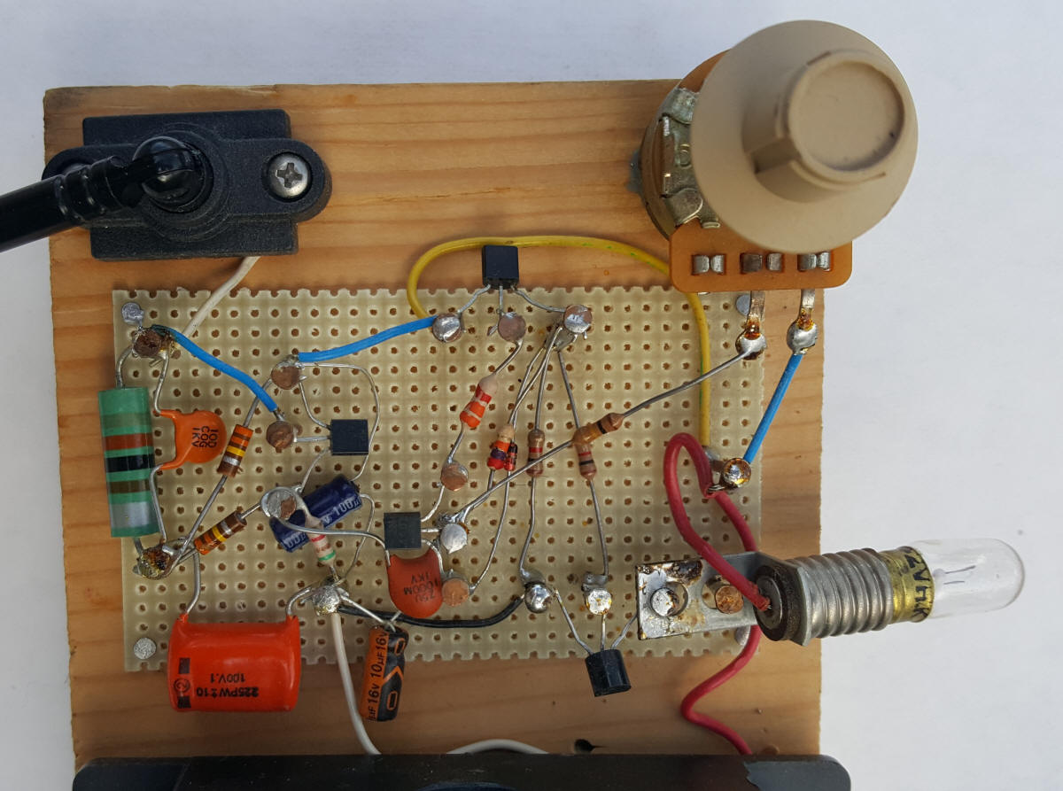
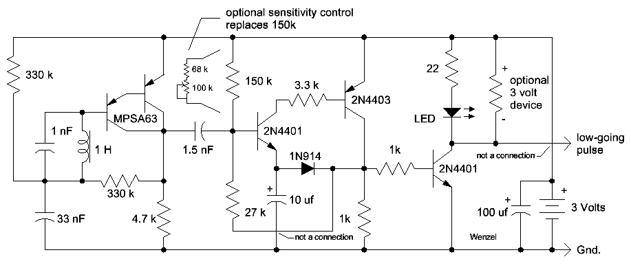
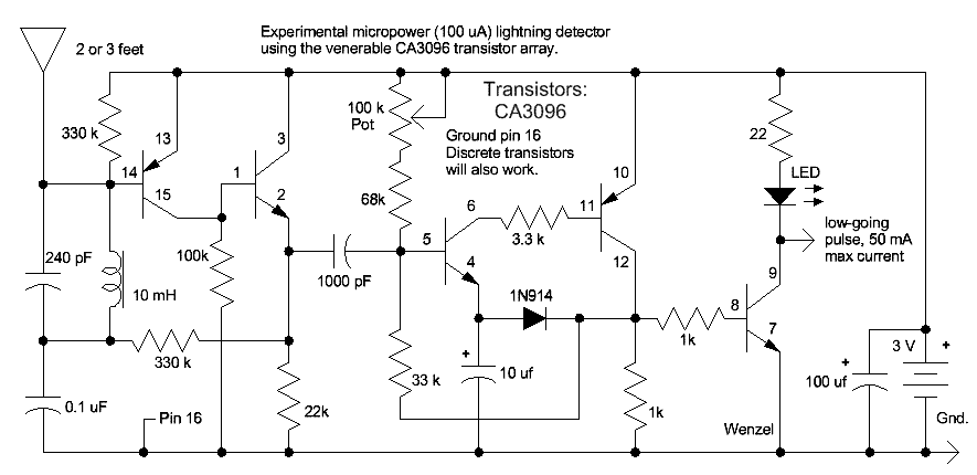
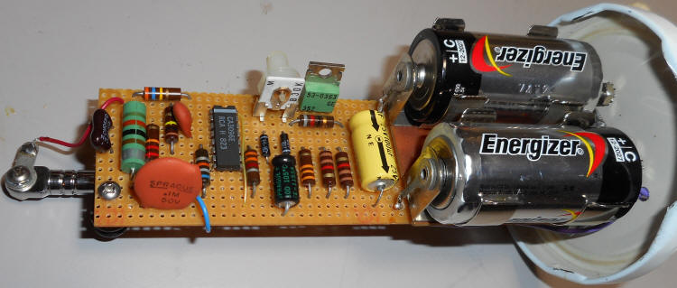
This new lightning detector circuit uses a single inductor tuned circuit to receive static pulses from lightning at a frequency near 200 kHz. The need for a tapped tuned circuit is eliminated by employing a very high input impedance RF amplifier that uses a darlington transistor. The amplifier is micro-power and the whole circuit draws only about 200 uA from two alkaline D cells, hardly denting the shelf life. The flasher portion of the circuit is similar to the earlier versions only the polarity of the transistors is reversed. As a result the output pulses momentarily go to ground from a normally-high state.
The schematic and close-up photos were made with the beginner in mind. Questions about the schematic can be answered by close-up examination of the photos. Try a magnifier utility for an even closer look.
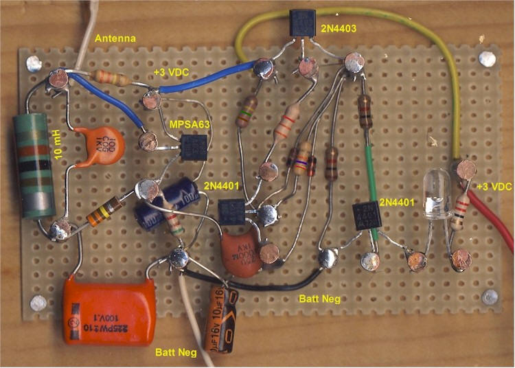
The 150k resistor in the base of the 2N4401 may be replaced with a series combination of a 100k resistor and a 100k (or greater) potentiometer to add sensitivity control. Simply adjust the potentiometer until flashing just stops for maximum sensitivity. The fixed resistor is plenty sensitive for most users. But, the receiver will only work well outside or near a window. A few yards of wire could be used to run an antenna out a window but connect a 47 pF capacitor in series with the wire at the detector end. Also, connecting a good ground will improve the sensitivity. Keep the unit away from electronic or electrical appliances and wiring for best performance.
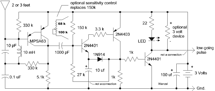
A common mistake is to select a 10 uH choke instead of a 10 mH. The large green choke in the photo is typical of the size and markings to expect. Color bands are brown, black, orange. A wide silver band often indicates the beginning of the color code.
Some of the other parts in the prototype were chosen to make it easy for the beginner to see the values. For example, the large .1 uF "orange drop" can be a tiny ceramic type. Parts may be in odd positions, too. The orange 10 uF is twisted to make the markings visible and other parts are oriented to make viewing easy.
The 100 uF shown across the battery is the blue part right below the MPSA63 in the photo below. Notice how it isn't right by the battery connections. Sometimes the position of a component relative to others is important but that information is often not on a schematic unless specifically stated. Schematics aren't usually physical representations; they just show which legs of the various parts are electrically connected. Schematics are usually accompanied by assembly drawings as part of a complete design especially when layout is critical. The point is to not take schematics to be mechanical layout instructions although they often are a fairly good start. On the other hand schematics generally aren't intentionally misleading about a good location for the part but a little electronics experience helps a great deal when there's only a schematic to go by.
The parts are not particularly critical. The darlington PNP transistor may be a different number, as may the other transistors. The diodes can be any silicon switching diode, like the 1N4448 (or probably any orange one you have). An amber LED with a 22 ohm resistor draws about 30 mA with fresh batteries. Vary the resistor to achieve the desired LED current for other colors (connect the LED and resistor to the battery through a current meter to select the value). The output transistor can sink several hundred mA, so several LEDs or other loads may be connected in parallel. The head from a cheap LED flahslight that uses two cells will be really bright! The pulse is pretty short to save power and for quick response, but for longer pulses, increase the 10 uF capacitor value. You might want a longer pulse to flash a 3 volt incandescent bulb (my favorite). Actually, I'm using a 1.5 volt bulb and it's really bright (not shown in the photos), even with this short pulse! I have lots of them and I'm sure I'll need to replace it fairly often.
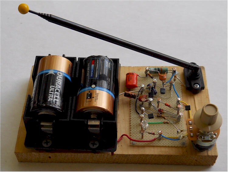
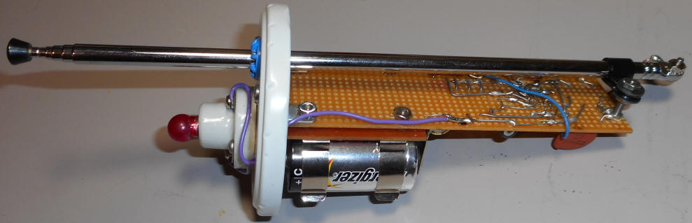
Below is a close-up with the sensitivity adjustment option and an incandescent bulb. The construction technique was chosen to make it easy to follow the wiring. Normally, the leads would be stuck through the holes and wired on the other side of the perf board. I used the perf board simply as a guide for copper nails driven into a pine board - strictly to make it easy to see all the connections. The perf board serves no purpose beyond visibility, so one could also use nails and wood for the assembly. The copper nails from the home improvement store really solder easily, by the way.
The image below is with an LED and no pot (but with the 150k resistor added). I made several image edits for clarity and to correct mistakes; they're not perfect but I think the connections are clear. Ignore the diode to the left of the 27k resistor; it has been removed from the schematic.
Marcos in Brazil made a video of his detector.
![]()
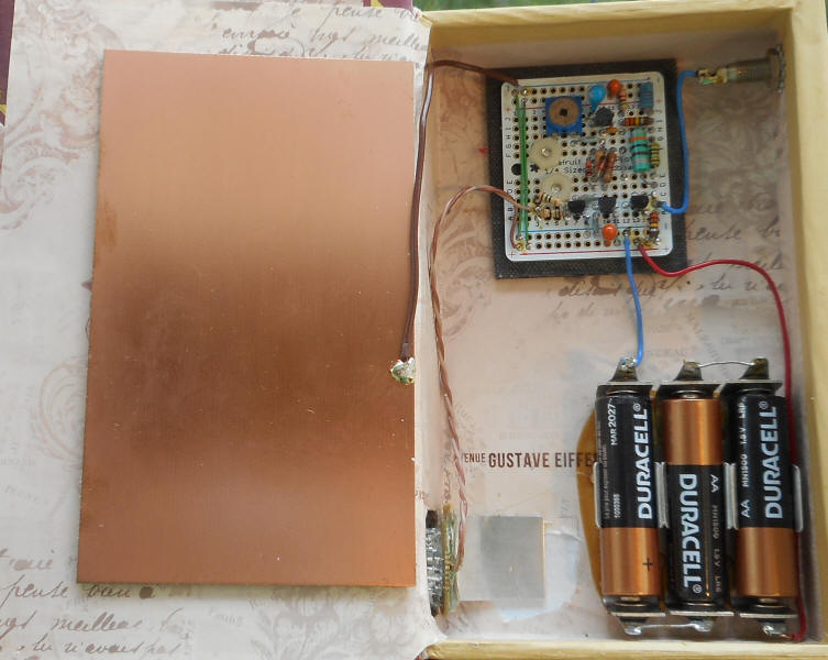
Here's a version I built into a "fake" book I found at an art store. The copper PCB is connected to the circuit ground to act as a counterpoise for the antenna, increasing sensitivity. The lightning bolt was cut with a sharp knife then filled with blue-dyed epoxy. The antenna connects to the pin jack. I used a cheap flashlight head for the LED - I used too much blue dye in the epoxy so I need a bright flash!
|
![]()
Note: The magnetic versions are more sensitive to distant lightning but they are fairly dead to piezo lighter impulses - those lighters don't emit much energy at 5 kHz the way a lightning bolt does. Same goes for my "lightning simulator." On the other hand, the magnetic field emanating from the speaker of a small transistor radio will do the trick! Just tune in a station and hold the speaker near the end of the coil.
With minor modifications it's possible to replace the telescoping antenna with a solenoid type inductor. One could use a ferrite loopstick operating at radio frequency but I've decided to tune this antenna to about 5 kHz. The resonant tank rolls off high-frequency noise and the circuit rejects lower frequency line-related hum. The lightning impulses ring this tank like a bell, easily seen on the collector of the darlington with an oscilloscope.
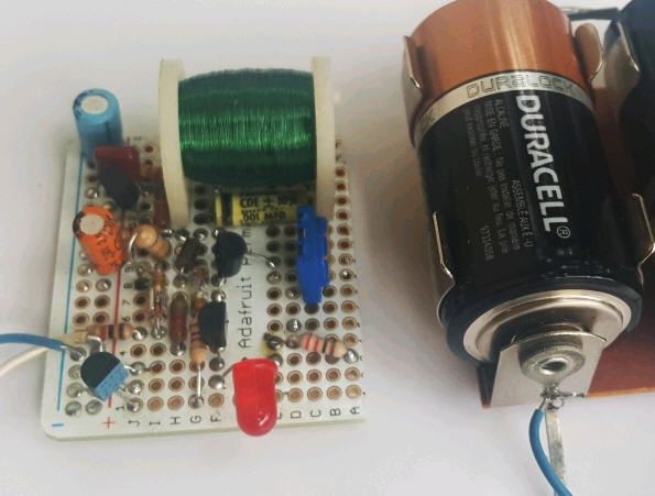
The 1 Henry inductor and 1 nF capacitor resonate near 5 kHz. Choose a value of capacitor that resonated your inductor around 5 kHz (not particularly critical). The inductor needs to be a straight solenoid type with no magnetic shielding on the ends. My prototype's inductor is from the high-voltage generator in an old CDV-715 radiation survey meter. The inductance should be between about 50 mH and 1 H. Typical inductors are shown below:
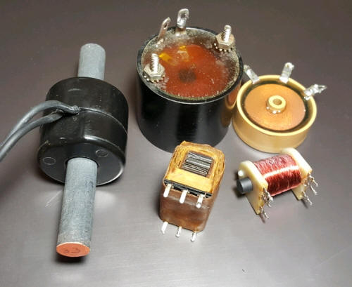
Bobbins from power transformers may also work but the core must be removed and optionally replaced by a ferrite rod or audio transformer laminated iron (only a straight "solenoid" core so that the external field gets in). The black coil above is from an industrial solenoid and the large #33 Amadon core brings the inductance up to nearly 1 Henry. I'm using the tiny one on the bottom right with good results. The pretty beige coil (an eBay find) measures about 50 mH. Use a good quality film or NPO ceramic capacitor to resonate your inductor. You can't use toroids, pot cores, or other cores that close the magnetic path back around the coil. You can probably use a relay coil if you remove all the metal pieces. Hook your prospective coil to a high-gain audio amplifier and if you hear distant lightning crackles you probably have a good candidate (assuming a storm is within a hundred miles or so). When indoors loud AC hum is another indication that the coil might be suitable.
Hook the inductor and capacitor in parallel across your scope and apply a signal through a 1 megohm resistor with an audio generator to see the resonance. Or use the lightning simulator and observe the frequency of the ringing on the collector of the darlington (practical with a digital oscilloscope). I just looked at the ringing caused by nearby lightning.
![]()
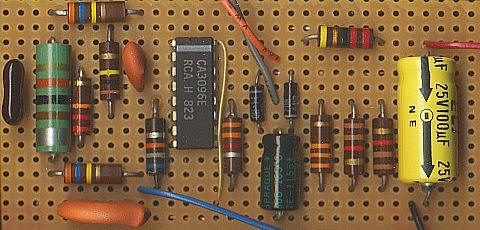
Here's another version that replaces the darlington transistor with a compound transistor consisting of a PNP and NPN transistor. This change allows the use of the venerable CA3096 transistor array. (Ordinary small-signal transistors may also be used. ) The 10 mH resonates with about 250 pF around 100kHz, a quiet frequency now that Loran-C is gone:
Since the CA3096 is pretty ancient I decided to use "period" parts for the rest of the components:
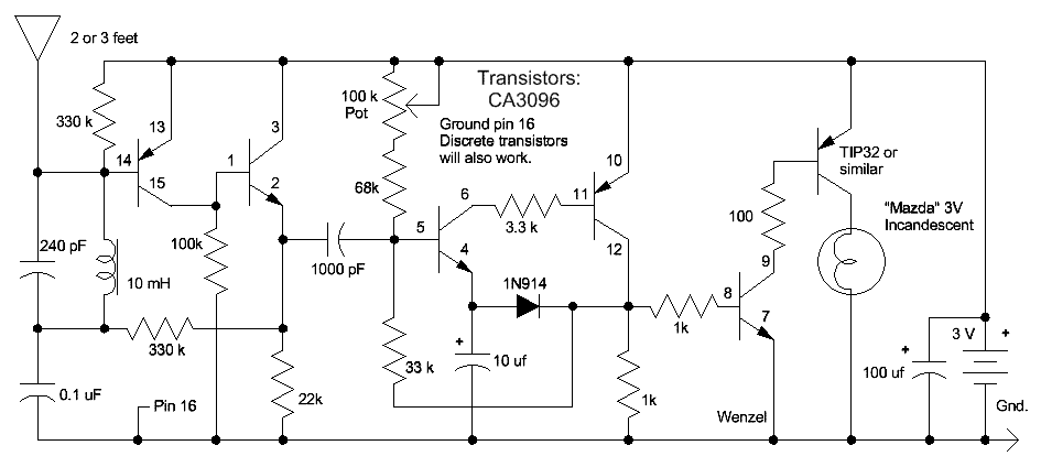
I then decided it needed to flash an old "Mazda" (GE trade name) 3 volt light bulb but the transistor in the array can't handle the current. I added an old green (PNP) GE power transistor to handle the additional current. Good design practice would suggest adding a 1k pull-up resistor at pin 9 or the power transistor base to plus but it's really optional and it didn't fit nicely. Some of the resistor values differ from the schematic but most aren't critical.
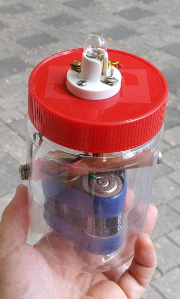
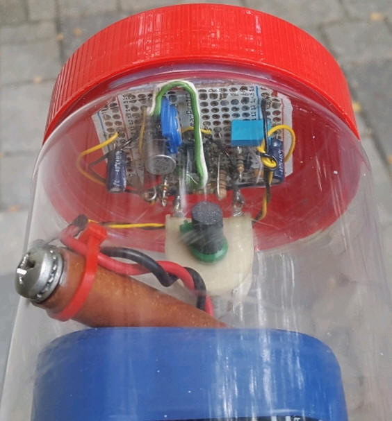
I borrowed Lennie's jar packaging approach so that the old components would be visible (otherwise, what's the point? : )
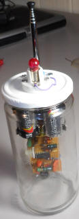
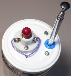
I placed that batteries near the top and secured one end of the battery holder directly to the lid for strength.
![]()
Don't build this one! Unless you just like experimenting. The idea is to rectify more of the pulse, making the light flash longer for larger bolts (more "area under the curve"). It works great in my old house, except when my coffee maker is running. But too many appliances and other sources in many houses (like my new one) produce competitive signals that will cause the thing to light up all the time unless the sensitivity is set too low. It's better to detect the quick lightning impulses that stick up out of that low frequency din. I'm working on yet another detector that will operate just below the BCB (where appliance makers are forced to keep the noise under control to avoid BCB interference). It will probably be nothing more than the earlier versions tuned higher in frequency, possibly with a 455 kHz IF transformer.
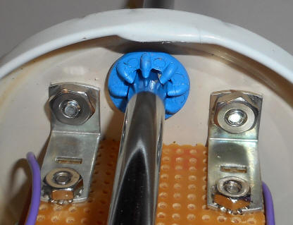
Here's a schematic using a typical "micro-power" op-amp. Choose an op-amp with just a few 10's of microamperes supply current to preserve battery life.
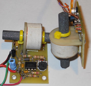
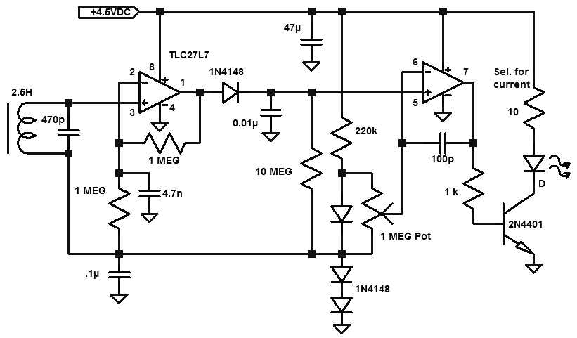
The coil and ferrite rod are from two eBay finds and measure 2.5 Henry shunted by 90 pF. I believe the coil is for pinball machine solenoids! Adding the 470 pF brings the resonant frequency down to 5 kHz, a great frequency for lightning energy but also just about as fast as this op-amp can go. The first op-amp is running "open-loop" since the gain-bandwidth and output slew rate can only support a gain of about 20 to 30 at 5 kHz. If you choose a much faster op-amp, add a resistor (around 22k) in series with the 4.7 nF and increase that capacitor to 0.1uF so that the gain is set by the resistor ratios. This micropower op-amp is slow but it draws only about 20 uA so the circuit can run on 3 C-cell batteries for quite a long time - except - it's so sensitive that it flashes quite often. I'd turn down the sensitivity, frankly. Right now it's flashing in response to a storm in Louisiana and I'm in Austin, Texas. That's just too much sensitivity. This prototype draws 24 uA when not flashing.
Or run it on a power adapter, preferably linear to avoid possible interference from a switching regulator. Add a 5 volt linear regulator (LM7805) if necessary. I prefer the power hungry incandescent bulb; they just look better in this application, at least to me. The bottom two diodes provide a little positive voltage to bias the op-amps even though these particular ones can look below ground a little. I was a little worried about large signals exceeding the negative voltage input rating and I want plenty of swing to turn on the detector diode. It's tempting to use a micro-power voltage reference there. The top diode in the string generates a threshold voltage for the second op-amp that acts like a comparator. The horizontal diode rectifies the 5 kHz ringing signal from the tuned circuit and the .01u and 10 megohm stretch the detected pulse for a bright flash. The time-constant is plenty short to see lots of quick flashes in succession. Strong pulses light the lamp for longer. When using an LED the time-constant could be shortened by reducing the .01 uF capacitor.
I stuck it in a peanut butter jar. A large standoff holds three D-cells taped together at the bottom of the jar and the circuitry is in the lid. The lamp screws into a Leviton socket so I can unscrew the bulb to save the battery during busy storms. One could replace the 2N2219 with a VMOS transistor (with very low turn-on voltage) and unscrewing the lamp would result in extremely low current even during a busy storm since there would be no base current (about 3 mA) during flashes. Even so, these batteries will last for years in my experience so I just soldered them in series, no battery holder and no power switch. It immediately started flashing and, sure enough, a storm is approaching from the northwest.
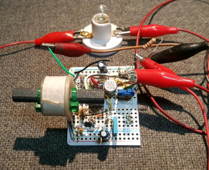
Here's another application for this op-amp version:
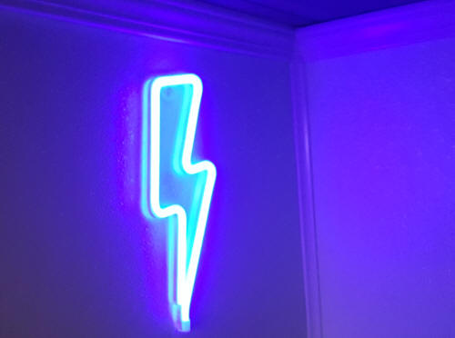
That's a large LED lightning bolt lamp I found on Amazon. (Watch out; there's a smaller, identical-looking bolt (just a few inches tall) but I highly recommend the larger one that's about 30cm.) I removed the battery holder and added a 6.8 ohm resistor to limit the current (it seems to like around 300 mA). It's on a wall in my basement lab and I have to say it's pretty spectacular when a storm comes. The bolts cost about $16 IIRC. I'm regulating the 5 volts to this version with a linear 3-terminal regulator powered by 12 VDC from my security camera power supply. By the way, don't plug this bolt into your modern USB port on your computer. I'm convinced the wiring is incorrect with the USB 5 volt line connecting directly to the LEDs (and not through the 10 ohm resistor in the battery compartment). A higher-current USB output can therefore force too much current through the LEDs destroying the bolt quickly. Hopefully the manufacturer will discover the error. Note the reviews by unsatisfied customers due to premature burn-out. Older USB ports will current-limit around 500 mA but that's a bit high, too.