
The battery and resistors generate a negative voltage near 100mV which is a good value for the 1N5711. Other diode types may need a different offset correction and the 82k value may be varied to give a correct reading when measuring a several volt RF signal. A 200k potentiometer may be substituted for the 82k resistor if an adjustable offset is desired. If an RMS readout is desired, add a 4.15 megohm resistor in series with the 10 megohm meter. (A 3.9 meg. in series with a 270k will work well.) Fig. 3 shows a differential version suitable for measuring the RF voltage across a component in a circuit. The probe should give the same reading when the leads are reversed.
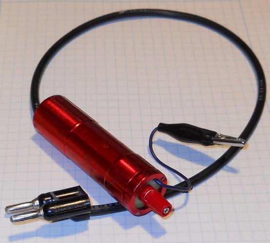
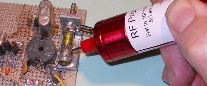
Here's Fig. 2 above built into a cheap LED flashlight case. I used an old 1N60 germanium diode for the detector and the 82k was just about right. (Some modern 1N60 diodes are actually Schottky types and may behave differently. Look for tarnished legs and an older diode style to duplicate this probe exactly - not that it matters much - Schottkys work, too.)
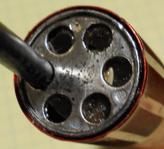
I removed the flashlight's push-button power switch and replaced it with a disk of PCB material holding a miniature binding post. The disk is held in place by epoxy. A ground lead also passes through a hole in the PCB disk (blue wire tied in a knot). I found a scrap PCB with a useful set of holes for the components and secured it with the nut that comes with the miniature binding post.
The battery is held by a 3/8" ID plumber's cone washer glued into the LED housing using contact cement. The AAA battery is a tight fit and needs no other support but a dab of contact cement in a place or two wouldn't hurt. Put a small disk of tape over the negative terminal of the battery before inserting it in the washer to prevent it from making contact with the LED housing (or stick the battery's positive end in the washer). The coax meter lead braid is soldered to the 1 megohm and 82k resistor - that black wire in the close-up battery picture is removed - the coax braid solders right there. You can see some contact cement inside the red case that held the LED housing - I had to pull it apart as I forgot to take a picture! This is a cheap probe that should last for many years without changing the battery so I consider it expendable.
After checking that it was giving the right readings for the peak voltage at 10 MHz I added a 3.9 megohm resistor in series with the meter output to drop the readings to RMS (13 dBm reads 1 volt). Don't forget, the circuit relies on the meter presenting a 10 megohm load.
Performance. The probe is quite flat in response from very low frequency to over 100 MHz. It actually increases output above 100 MHz, probably due to layout-caused resonance. It's responsive to quite a high frequency so it can be used for peaking circuits beyond 100 MHz. The table below was made at 10 MHz. Error starts at 0% at 13 dBm since that's where I calibrated it. Higher voltages read accurately.
| dBm | Vrms |
Meter |
% Error |
| 13 | 1.0 | 1.0 | 0 |
| 10 | 0.71 | 0.71 | 0 |
| 7 | 0.50 | 0.51 | 2 |
| 4 | 0.35 | 0.37 | 5 |
| 1 | 0.25 | 0.28 | 12 |
The probe detects signals as low as -25 dBm so it can be used for peaking small signal circuits albeit with inaccurate readings below 0 dBm.
Other ideas: A second DC-biased diode may be used to generate a temperature-tracking reference voltage to drive a differential amplifier. Another scheme is to add the second diode in the feedback path of a voltage follower as shown below:
A fifty ohm resistor is included in the schematic but a much higher resistor, say 100k, may be used for a high-Z probe. The circuit works well as a linear detector for signals above about 100mV. The resistors may be connected to zero volts, allowing the use of a single power supply voltage but choose a "rail-to-rail type op-amp.