
![]()
Here is a phase-shift audio oscillator with excellent distortion characteristics thanks to "softened" diode limiting provided by the 1N914 and resistor divider and degenerated gain provided by the 68 ohm emitter resistor. For minimum distortion, increase the 68 ohm resistor to a point just below where oscillation stops. A simple buffer may be added for driving lower impedance loads. The output amplitude will be about 5 volts p-p but one of the 1N914's 10k divider resistors may be changed for a different output amplitude. The circuit will work well with a power supply voltage other than 9 volts but the 68 ohm resistor may need adjustment.
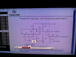
Images from the movie. Sorry about the pause bar. I wonder how Nokitel uses a phase-shift oscillator in a cell phone.

A digital guy trying to figure out an analog circuit.
or
"How do I hack a cell phone with this?"
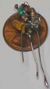 |
The circuit can be built in the "blobular cluster" style (to coin a phrase) and potted with epoxy mixed with a little model airplane paint. Use quick-setting epoxy and, holding the circuit by the legs, keep rotating the blob near the end of the cure cycle to get an even coat - quite an art form! The finished module looks quite professional, not unlike many dipped caps. | 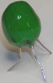 |
![]()
Here is a two-transistor Wien bridge oscillator using an ordinary night-light bulb for stabilization. The output is about 6 volts p-p and can drive fixed loads as low as 2 or 3 thousand ohms without additional buffering. A 10 k amplitude potentiometer with the wiper going to a high input impedance output amplifier would make an excellent load. Use a 1/2 watt or greater for the 180 ohm collector resistor.
Excellent distortion is achieved by adjusting the 1 k feedback potentiometer until the output amplitude is about a volt less than the maximum level (with the pot set to the highest resistance). (Note" a reader suggests that the 1k pot may need to be a higher value in some cases; try a 5k pot.) Wait a few seconds between adjustments to give the bulb time to stabilize; the audio signal actually heats the bulb's filament causing the resistance to go up which controls the loop gain. You will see the signal bounce a little as the bulb gains control. This simple version of the popular Wien bridge oscillator uses feedback to hold the junction of the two RC networks (base of first transistor) near zero volts (100 mV p-p) and the ends of the RC networks move in opposite directions like a see-saw.
With the resistor values shown, the frequency may be varied from a few Hz to over 60 kHz by selecting a value for C between 1 uF and 47 pF. The frequency will be reasonably close to 1/ (6.28 x RC). R may be varied also for additional range but values too low or high may cause problems. The 7-watt bulb may be replaced by a smaller type with similar resistance (more than 50 ohms) but the long time constant of the larger filament is helpful when generating very low frequencies.
|
The 100 uF output capacitor may be smaller if very low frequencies are not generated. | |
|
The 22 pF is added for stability and may be eliminated depending on the transistor types and circuit layout. A larger value may be needed in some cases. | |
|
The output is ground referenced with no DC offset. | |
|
A load change may require readjustment of the feedback potentiometer. | |
|
The series RC may be switched if it is desired to have the resistors connected together. | |
|
A high gain transistor like the MPSA-18 for the first transistor will allow a much larger value for R, up to 1 Megohm. |
The circuit should draw between 18 and 45 mA, a value determined by the transistor gain and the value of R. Current outside of this range may cause distortion. The 1.2 k emitter resistor may be varied slightly to adjust the current consumption; shoot for 25 to 30 mA.
It should be noted that op-amps make great Wien bridge oscillators without significant impedance and bias concerns! There are dozens on the web and in manufacturers' application notes. But sometimes a couple of friendly transistors fit the bill perfectly.
![]()