Video and optical sensors are well-established as consumer products but here are a few ideas for unusual modifications and gadgets.
It's hard to beat a modern digital recording system that saves video and audio to a hard drive, either within the unit or on a networked computer. The software usually comes with the ability to sense motion which is great for saving disk space and making it easier to find interesting content. But, those motion detectors are notorious for not working well, especially when uninteresting motion is in the frame. The first project solves this problem by replacing the fancy digital motion detection with ordinary PIR sensors. Infra-red motion sensors tend to respond only to warm bodies and tend to ignore distant objects. A wireless PIR sensor aimed at the mailbox can start the recorder when someone approaches the box while ignoring the passing cars, with a little adjustment. They can be placed anywhere and can even start the recording when nothing is moving within the frame. There are lots of times when the motion that is desired to trigger the recording isn't directly related to the desired video or is in the midst of other motion. Suppose you suspect a peeping Tom is visiting your house. Position the PIR sensor to pick up family members entering the bathroom but locate the camera outside to catch the perp. in the act. This limits the recording length and makes it easier to spot suspicious activity, even if there's a lot of activity in the area.
There are any number of ways to control a recorder with an array of PIR sensors and the following circuits are for illustrative purposes.
Wired PIR sensors are inexpensive and simple to use. But, the outputs may not be ideal for running a recorder. The following circuit turns a momentary low-going pulsed signal ("chime" mode) into a 60 second record switch closure.
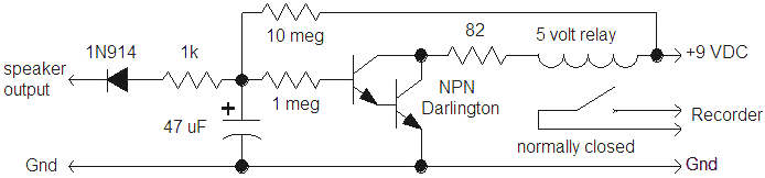
The relay's normally closed contacts are used (closed with no coil current). The circuit energizes the relay so the contacts stay open until the chime signal from motion detection turns off the transistor. Note that the red speaker wire is disconnected to silence the speaker. Most detectors have an LED and that signal may also be used. If the alarm pulse is positive-going, simply reverse the diode, connect the 10 megohm to ground instead of plus and use the normally open contacts. The circuit as shown draws current so a line powered supply is needed, typically a small 9 volt molded type. A lower voltage relay (5 volt, in this case) may be used if a resistor is added to drop some of the voltage. The 47 uF capacitor gives about a minute of record time after the trigger and the value may be adjusted for more or less record time.
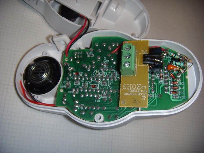
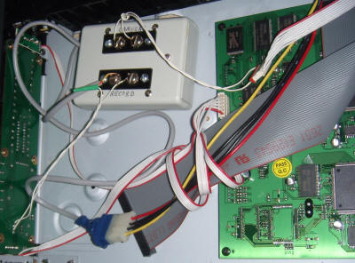
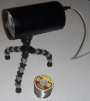
The photo shows a typical PIR sensor with the circuit installed. In use, a DC power supply is connected to the 9 volt battery snap. The diode is connected to the pad for the red speaker wire. This pad is normally high (9 VDC) and pulses low to drive the speaker. The relay contacts are normally open so several sensors may be paralleled to operate the same recorder. For example, a four camera recorder might have four sensors, one for each camera. Or a combination of video motion sensing and PIR sensing may be employed.
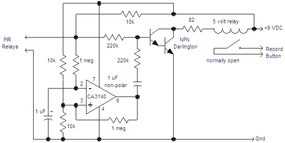
Some recorders may require additional circuitry to control. As as example, my recorder will start recording with a quick tap of the record button. But holding in the button will stop the recording. The following experimental circuit holds in the record button by shorting it until one of the PIR sensors triggers. When one of the PIR sensors shorts the 'PIR Relays' inputs, the relay opens and the record button is no longer shorted. After a short delay, the op-amp switches positive and momentarily closes the relay to 'tap' the record button to start recording. The series 1 uF capacitor turns the high-going level into a short pulse. A higher value may be needed if the relay doesn't stay in long enough or smaller if the relay stays in so long that the recording stops again.. The recording continues until the PIR relay opens and the record button is once again shorted by the relay; simulating your finger holding in the record button. It's fine to keep the record button held in until the next recording session, mine's been working like that for a year. The normally open relay contacts are simply connected across the back of the record button and power for the circuit is borrowed from the same molded supply that runs the various PIR motion sensors.
Other recorders may require different techniques. Some may work fine with the simple switch closure provided by the PIR sensor circuit. Other switch closures from beam break gadgets, vibration sensors, door switches, etc. may be used to trigger a timer circuit, too.
In general, avoid wireless cameras that transmit video, especially on 2.4 GHz. They tend to interfere with wireless routers. On the other hand, there are excellent wireless cameras that will work with your wireless router. Here's a picture of our hallway from a WiFi camera that cost under $100:
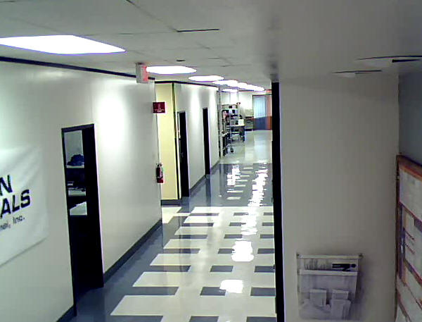
That's a nice image for such a cheap device and I grabbed this image off the web from home. Digital video sure beats analog, especially when an RF link is involved! Pan, tilt, and zoom versions cost a lot more but can be quite handy for 'remote viewing' (no psychic abilities needed). Nothing says that a wireless router must be connected to the Internet, either. One could have a private network of cameras all connected by a central router viewed by any computer within range of the router using local IP addresses.
Tiny video servers that accept up to 4 video sources and an audio source are available for well under $100. These gadgets hook up to the network and serve videos to anyone who knows the IP address! They're great for those of us who have lots of old video cameras or old analog camcorders looking for a purpose to exist. Old camcorders make great security cameras with excellent optics and they're often considered junk. Ordinary web cams are dropping in price and improving in quality but a USB connection to a networked computer is needed. On the other hand, who doesn't have an old laptop or two laying around!
As mentioned immediately above, routers can be used with or without connection to the Internet. Private networks can be easily created by strategic positioning of a router and antennas. High-gain antennas on the various remote computers can achieve excellent range if the router is outside, in the clear. When I was a kid, my friend and I stretched a speaker wire between our houses and set up a Morse code system. Today, I would just place a router in the attic near the neighbor's house and we would have full-bandwidth video and audio - no Internet required! Networked gadgets are growing in number and variety and simply leaving the Internet disconnected removes one of the most worrisome security issues, especially if you want to find a use for those old, slow Windows 98 computers.
Isolated wired networks are useful, too; nobody will hack into them. Old, low-power laptops can be plugged in to the power (since the batteries are probably shot) and hard-wired to a router to form a secure network for internal uses like data acquisition, alarms, video and audio distribution, control, and even a simple video intercom. Even an old Windows 3.11 laptop with a black and white screen is safe on such a network since there is no Internet or wireless connection.
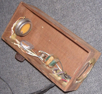
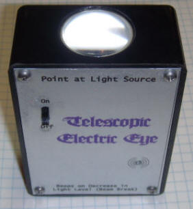
Cadmium-Sulfide photoelectric cells change resistance with changing light levels and are useable over a tremendous illumination range. A simple CdS cell placed in the focal plane of a lens makes a telescopic 'electric eye' that can function at midnight or noon, with the appropriate circuitry. To illustrate the idea, consider the antique from my school days shown below. The box was for a famous cologne and the lens just perfectly projects images onto the photocell. A simple one-transistor blocking oscillator drove an external speaker. The pot was adjusted until the oscillation just stopped with my girlfriend's porch light turned off (across the street). When it was time for my friend to go home, her parents would turn on the porch light and beeping commenced. The simple single lens arrangement is quite directional.
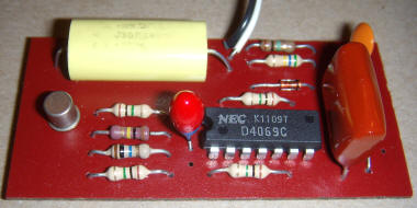
The circuit of this old keepsake isn't worth documenting so an improved version is constructed for general-purpose monitoring. The circuit below is a passive beam-break beeper that will let out a short chirp whenever something moves between the cell and a distant light source, typically a lamp or window.
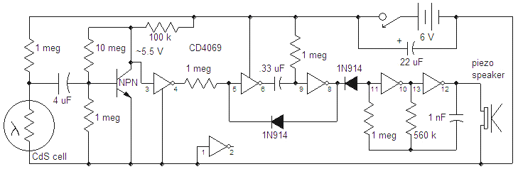
(The transistor could be replaced with the unused gate, linearized with a large feedback resistor to form an amplifier, but the current consumption will be above 1 mA.) The transistor preamplifier is 'starved' for current, barely pulling the voltage down on the 100k (should be within 1 volt of the power supply). Not only does this minimal bias save current in the transistor, it also keeps the first gate out of the linear region and total power consumption should be below 30 uA. The 4 uF is a non-polar type but it could be replaced with a 4.7 uF tantalum with plus to the CdS cell. The .33 uF may also be replaced with a tantalum type with plus to pin 9. The value determines the length of the beep. The beep frequency is determined by the 1 nF capacitor. The NPN may be an ordinary 2N4401 or 2N3904. Higher gain transistors will draw a little more current as they will pull the gate a bit lower. Shoot for a voltage around 5.5 volts on the collector. I used an old, lower gain transistor and the collector voltage is only a couple of hundred millivolts below the battery voltage. The resultant circuit current is only 14 uA and the sensitivity seems fine. One could 'play with' the 1 meg on the base to set the current for minimal current drain but leave a couple of hundred millivolts across the 100k collector resistor. Cover or disconnect the photocell when making the bias adjustments.
When the light illuminating the cell is interrupted, the voltage on the base of the transistor goes up, pulling the collector and first gate input low. Pin 4 jumps up, triggering the next two gates which form a monostable multivibrator. Pin 8 goes high for a second or so, reverse-biasing the 1N914, allowing the last two gates to oscillate. All gates are biased to be either fully high or low to save power when no trigger is occurring. Pin 8 could drive other loads besides the little beeper. Add a grounded-source MOSFET with the gate to pin 8 for controlling larger loads.
The lens is glued to one end of a PVC plumbing coupler and the photocell is glued into the other:
The coupler was widened slightly with a rotary hand tool sanding drum to accommodate the cell. The cell is a little behind the focal plane, but the widened, blurred image still falls nicely within the bounds of the sensitive area of the cell. These large cells were manufactured for outdoor lamp controls and other types will work fine.
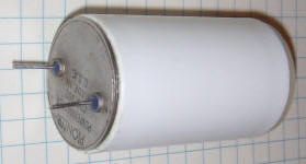
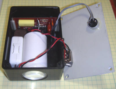
The circuit is built onto a piece of countertop laminate:
The board is held by two lengths of card guide in a phenolic case. A hole is cut in one end of the case for the lens using a sharp hole cutting bit for wood. The battery consists of two 3 volt lithium cells in the white holder. The label is made by reversing the artwork and printing it on overhead transparency film. After printing, the backside is sprayed with aluminum paint. I should have followed with a coating of urethane to protect the silver paint from the spray adhesive used to secure the label to the panel. The adhesive solvent marred the paint near the power switch a little. The resulting label is still attractive and very durable since the printing is on the back side.
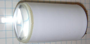
A fancy version of the telescopic electric eye is shown below:
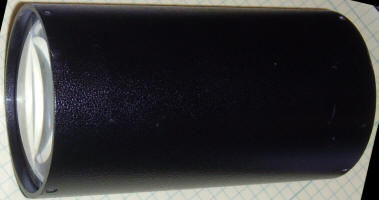
The 3" diameter lens focuses images on the back of the 6" tube where a large, high-quality cell is mounted. A quick test in the lab determined that a single candle at 18 feet lowers the resistance of the cell from well over 100 megohm to only 60,000 ohms; that's well over three decades of change from a candle across the room. The neighbor's porch light drops the resistance to 250,000 ohms which is pretty low for such a dim, distant light. This electric eye could count deer or spot prowlers using a neighbor's porch light or the corner street light.
A switch arrangement could be added to the circuit to switch the photocell with its bias resistor to make the circuit sensitive to increases in light level. This arrangement would be useful for spotting approaching cars or prowlers with flashlights. Even the prowler with a smoking habit would be caught!
The same sort of gadget could be made with photodiodes, phototransistors, selenium solar cells, old photo diode tubes, and even ultra-sensitive photomultiplier tubes. A flashlight reflector with a small cell at the focus could substitute for the lens with smaller devices like photo transistors. The output at pin 8 of the circuit above could be used to close a relay or solid-state switch to activate a wireless doorbell transmitter. Such a detector could be hidden near the edge of the property and aimed back at a bright LED or other lamp at the house. The beauty of an ordinary lamp, perhaps a low-power fluorescent, is that the 'direction' of the beam isn't obvious. In fact, one light could be used with a couple of detectors at each corner of the property.
For applications where an external power source is available, the 1 meg resistor above the photocell may be replaced with another photocell. Add a 3.3k in series to limit the current in bright environments. Mount the two cells in tubes pointed in slightly different directions, perhaps just a few degrees of angle between them . Or, simply mount them side-by-side in the focal plane of a lens; each cell will be 'looking at' a different part of the scene. The two cells will receiver about the same light level, biasing the center point to nearly V/2 where the sensitivity is greatest. This arrangement is extremely sensitive to the slightest change and can easily pick up activity from quite a range and the cells will automatically adjust the bias point for a very wide range of light level.
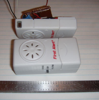
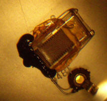
Photo below is a tiny door alarm in the process of being modified into a PIR motion sensor. The PIR sensor doesn't have the traditional light pipes and 'fly's eye' lens but it can easliy detect a passing warm body when 1/2 of the sensor is covered. The schematic and details are waiting development!