
See new results below
This experiment attempts to use ionizing radiation from two americium pellets from smoke detectors to continuously discharge a sense antenna for electric field measurements. As long as the ionization can conduct significantly more current than the bias and leakage current of the buffer amplifier the wire should stay "neutral" and be able to sense a static DC field, or so goes the theory. The circuit is trivial, simply a voltage-follower op-amp (TLC27L7) running on 9 volts connected to the sense wire through a 1 megohm just for safety (let's call it an "idiot resistor"). A 4.5 volt "artificial ground" made with two 1 megohm resistors biases the can halfway up. The high-value resistors and micro-power op-amp will run on a single battery for years.
I'm using the micro-power mosfet op-amp, the TLC27L7, simply because I have them and many CMOS types will work fine. The two americium elements support about 100 pA each (I just discovered after a better measurement) so that bias current of any CMOS op-amp should be plenty low for just one element; you shouldn't need two.


I mounted two smoke detector americium elements in an almond can with a pickup wire above them near the opening. This time there is no bias voltage on the can except for the artificial ground; the ions simply "connect" the op-amp to the sky's field by preventing charge accumulation. It's mounted under an awning pointed somewhat towards the ground but it still seems to work. The original idea was this to be the DC portion of a field mill with the faster stuff being sensed by an ac-coupled circuit and another sense wire. But it's pretty quick, as-is, and a frequency response network of some sort might be all that's needed. The real challenge would be to make one that weather and insects don't ravage.
The data is being recorded by my live SID recorder; ignore the red trace. I'm using my Meter DAQ Amplifier to boost and offset the voltages for recording.
The first plot shows a flat spot near the end is when I covered the open end of the can with a metal lid. A modest weather system has produced more noise and an overall higher reading. A cold front can be seen arriving at 11:00 just before sunrise on the second plot:


I positioned a metal plate hooked to a variable power supply in front of the sensor and was able to plot "DC" lines for hours. For a more serious attempt to make this work well, I'd use a DDS to measure the frequency response and then tailor the gain of the amplifier to compensate. I say a DDS because the frequency response is likely to be changing at very low frequency with the DC response being less than the AC response even below one hertz.
A rainstorm came through with no lightning and made the plot below (left). I copied the next day's data and added it to the previous plot, hence the overlapping top black trace. Yesterday starts at just before 5:00 and the clouds begin arriving in the early morning, around 14:00. Rain starts to fall at 19:30 (sudden rise). There may have been a little electrical activity around 0:00. I needed a good old lightning storm! I got the storm right before 9:00 UTC (plot to right) the next day. It clearly responds to the change in potential due to a thunderstorm and I'm sure a faster plot would be interesting.


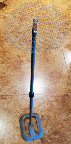
Many years later I've tried again using jAmaseis to record the results. A cooperative storm came through last night and I got the result below. The plot starts out near zero volts where it's been sitting for days and then trends negative as the storm approaches. When the storm was just about to be overhead the voltage dropped significantly and stayed down. The plot runs for 15 minutes - need to work on the axis labeling! A wind gust tipped over the temporary stand and the chamber hit the ground so hard it literally disassembled; there were many moving parts for a couple seconds! I had it well under the porch pointing straight out and down our hill. I'll mount one on the wall in the future. It turns out that the device will work well completely protected from the rain under an awning. The calibration might suffer but that's not important, really. When it was first installed it wouldn't hold it's value but would quickly drift back to zero as though the americium wasn't doing its job. It turned out to be a single strand of spider web bridging the sense wire to the can. There will be maintenance issues with these things! I'm thinking of snapping the almond can's cover on when there's no interesting weather. The photo to the right is another stand with an insulated disk of poultry wire. I can place that in front of the chamber and apply a DC voltage (relative to the house wiring ground) to verify that the circuit can sustain a DC output. Works great!


Another storm came and this time I secured the now-repaired mill under a large patio:


There were no extremely close lightning strikes but one flash was followed by thunder after a few seconds and that large negative spike resulted. The plot is made by JAmaseis driven by a PicAXE data taker supplying six measurements per second. JAmaseis "thinks" it's getting data from a device named "Sep."

Above is another storm that just passed over and the electrical activity is obvious. Again, no close lightning strikes. This plot is after days of straight lines. Notice the voltage is able to stay negative most of the time. I think the idea works! The sample rate is only 6 Hz so very fast stuff isn't plotted but earlier tests with a signal generator suggest the circuit can respond to microsecond events - more testing is needed with possibly a better way to drive the cable.
The technique shows promise for other "non-contact" potential measurements but it might be a bit fragile to leave outdoors and a single strand of spider web was enough to disable it. So the installation needs to be such that it is easy to brush out the interior. Covering the can when not needed (clear days, for example) is a good idea. I was curious how much current one smoke detector's americium bit could support and I realized I could place it inside the PicAXE ionization chamber to get a somewhat calibrated value. I measured 100pA, plenty to handle a CMOS op-amp's bias current and more than I expected.