
Note: the original schematic had an error connecting the Sinitsa/Normal to Vcc instead of ground making it a Sinitsa/Dead switch.
![]()
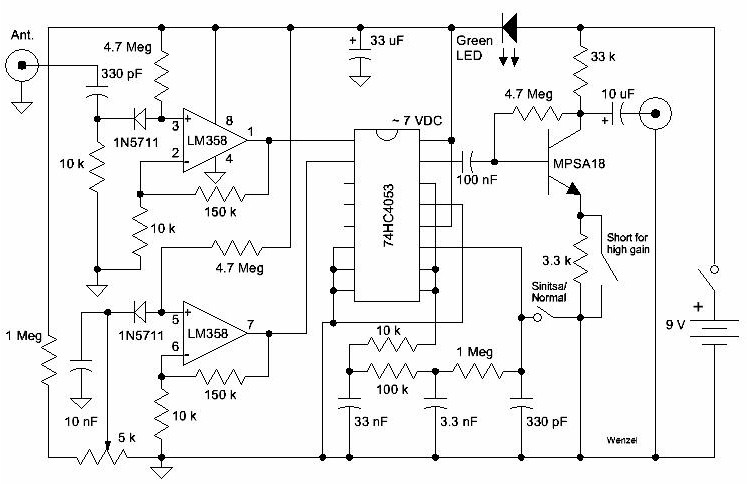
The Bug Duster is a detector for uncovering RF-based video and audio bugging devices. It has two modes of operation, an All-Band detector suitable for spotting many forms of analog and digital modulation and a "Pseudo-Sinitsa" mode of operation that can detect most forms of modulation, even dead carriers. The Pseudo-Sinitsa mode is based on the Soviet Cold War transmitter hunter called the Sinitsa. That machine used an RF diode to chop the incoming RF at an audio rate, imparting an AM modulation on the carrier. Subsequent filters and an RF amplifier then fed an ordinary AM detector and audio amplifier. The Bug Duster uses two diodes to accomplish nearly the same results. Instead of turning the RF on and off, an analog switch selects the voltage from one of two detector diodes at an audio rate, one diode detecting incoming RF and the other acting as a reference. The result is nearly identical to the old Sinitsa since the reference diode sits at the same voltage the detector diode would drop to if the RF were removed. In fact, an offset voltage may be applied to the reference diode to "dial out" background RF, typically commercial broadcast signals (the 5k potentiometer).
The signal comes into the antenna connector and is immediately detected by the biased detector circuit used in the other techlib All Band receivers. The op-amp amplifies the DC from the biased diode by 16 to get a voltage around 3 volts. Make sure to check the voltages on pins 1 and 7 to make sure the voltage is a couple of volts away from ground and Vcc. Also verify that the zero circuit can be adjusted to match the voltages with the pot near the ground end of adjustment. When balanced, the two op-amps present the same DC voltage to the analog switch (74HC4053). (If you prefer, you can eliminate the green LED and run everything on 9 volts.)
The 74HC4053 uses one of the switch sections as an audio phase-shift oscillator to toggle the other two switches. Only one of the toggling switches is used (pins 1, 2 and 15). The analog switch connects the two op-amp outputs to the MPSA18 transistor amplifier at an audio rate so if there is any DC difference between them, there will be a small square wave of audio. The output of the amplifier is only suitable for driving a crystal earphone or amplified headphones. Alternatively, replace the MPSA18 amplifier with an LM386 audio amplifier for more output drive
There's a 3.3 k resistor in the emitter of the MPSA18 to lower the gain when "bug sweeping" because high gain will require constant readjustment of the zero since ambient radio signals change from point to point in a room. Short that resistor with a jumper for high sensitivity. The resistor value may be lowered for intermediate gains. Also, connecting pin 11 of the 74HC4053 to ground will kill the oscillation and leave the switch selecting audio from the detector op-amp. This "normal" mode is basically the original All-Band receiver using an op-amp for audio gain.
Now how do you sweep a room for video bugs without alerting the enemy that you're on to them? That's where the feather duster comes in. It's perfectly normal (in cleaner homes, anyway) to dust every object in a room. A hidden antenna amongst the feathers in the duster picks up signals from any nearby transmitter and sends them to the receiver through a thin piece of RG174 or similar cable running up the sleeve. One can use a long drill bit to drill right down the middle of the handle of the typical 99 cent feather duster. I actually used a long, thin Phillips screwdriver blade in my electric screwdriver - it literally melted its way through. I pushed the feathers back to reveal the antenna and the lip of a plastic cone that holds the feathers in place (part of the duster). The coax center conductor is soldered to the end of the antenna and the connection is covered with heat shrink tubing. The antenna extends only a few inches into the handle and it is held in place by shoving some epoxy putty or Sugru putty into the funnel section around the antenna. I used an additional glob of Sugru to form a strain relief for the cable exiting the duster.
![]()
![]()
![]()
Here's how it might look with the sleeve pulled back. Okay, something better than a rubber band is needed. The crystal earphone would run up the sleeve to the collar.
![]()
![]()
The circuit was constructed using the "dead bug" technique, a seemingly appropriate construction method for a bug detector. There's nothing particularly critical about the layout; I just started building, keeping everything crowded so as to not run out of room. I polished a piece of copper clad board and then sprayed it with Testors transparent red paint to keep it looking nice. Solder seems to melt right through.
![]()
That black switch in the middle near the bottom is the "Sinitsa/Normal" mode switch. If you look closely, you can see two horizontal wires right beneath the metal transistor. Those are the legs from the 3.3k resistor, one coming up from the ground plane. I bent them like that so that one of those 0.1" jumpers used on computer boards and hard drives could be slipped on for high-gain mode, shorting the 3.3k resistor. A Molex connector with a lower value resistor could be slipped on for an intermediate gain value. The metal transistor obviously isn't an MPSA18 but is a similarly performing 2N2484. I used carbon composition resistors just for nostalgia. The green LED drops about 2.4 volts, keeping the voltage on the 74HC4053 near 7 volts but a reader points out that this IC is rated for 10 volts so the LED may be replaced with a short.
I'm going to put on my thinking cap to come up with other applications for the self-commutating analog switch. There's another unused section so it's really a self-commutating DPDT switch. Simple lock-in projects come to mind.