This article began as a design guide for hyper cranial erogenic field generators, however, your primitive earth brains are completely unable to respond to erogenic fields in the 100MHz region. I personally had a brain upgrade (for purely medical purposes of course) so I am able to respond to these fields. But for you poor primitive earthlings we must resign these devices to the only use you are able to find for them – short range transmitters for your FM broadcast band. Oh – and the rumour that I bought a house next to an FM broadcasting station is completely false. Well, mostly.
IMPORTANT NOTICE:
We, as engineers, do not build miniature transmitters for the actual purpose of using them. They are engineering challenges intended to illustrate principles. We do not advocate their use for a couple of reasons.
Firstly, their use probably contravenes radio regulatory and licensing legislation of your country. In other words using one, for whatever purpose, is probably illegal.
Secondly, if used as a covert listening device, they probably contravene the privacy laws of your country.
Lastly, it is simply WRONG to use them for clandestine purposes.
Readers build and operate this circuit entirely at their own risk and it is the reader’s responsibility to determine the legality (or otherwise) of the use of this circuit in their own country or state. If the reader chooses to ignore this warning, we hope they will at least take seriously the nuisance they can cause when operating illegal transmitting circuits, and heed the suggestion for ways to improve stability and reduce the risk of interfering with legitimate services.
Anyone who has constructed any of the numerous transmitter circuits on the web
will have found most of them to be unstable. The reason – they lack crystal
control. Wide deviation FM (as employed on the FM broadcast band) is not
amenable to crystal control - the frequency deviation is too great and a crystal
oscillator simply cannot be made to deviate that far. The answer – a phase
locked loop – is complex and too big an undertaking for most hobbyists.
The stability of these circuits is made worse by the usual choice of antenna – a
piece of dangling wire. But even a rigid whip antenna doesn’t improve matters
very much. The simple presence of an antenna causes the immediate RF environment
to become part of the oscillator circuit with the consequence that any change in
that environment results in a change in load and a shift in transmit frequency.
We present here the loop antenna - something of an outsider until quite recently
when it found application in the large number of MP3 transmitters on the market.
The loop is fairly unique amongst the antenna types in that it doesn’t depend on
a ground ‘ballast’. The circulating currents in the loop radiate RF energy, most
of which destructively interferes for a loop of a practical size, but radiate it
does nonetheless.
The loop's independence of a ground or counterpoise brings a very considerable
stability dividend - it is almost independent of the RF environment. As a
result, surrounding objects (including you) are no longer part of the radiating
process. This yields a transmitter that doesn't shift transmit frequency if you
come near it or pick it up! You can even touch the 'cold' side of the loop
without significant frequency shift!
To be effective, a loop antenna needs to be resonant. But if the loop is
substituted in place of the transmitter's usual tank inductor, then resonance is
assured regardless of the actual transmit frequency. The result is a very
compact transmitter that is stable AND has useful range. Something of a dream
come true really!
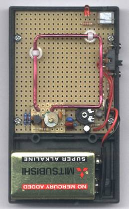
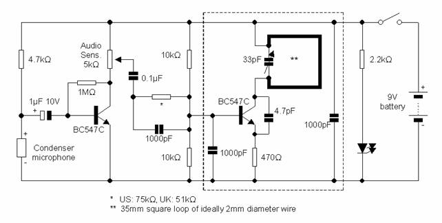
Radio microphone using loop antenna
The core transmitter components (those inside the dotted box)
are mounted on a sub-board. This is for no other purpose than to move the
critical transmitter components out to a mid-depth position in the case. Note
too how the ‘hot’ end of the loop (that connected to the second transistor
collector) is more central than the ‘cold’ end (that connected to the supply).
These two stratagems serve to put distance between these key components and the
user’s hand.
Plastic pillars and tie wraps serve to secure the loop to the main board,
thereby preventing movement of the loop in the event that the radio microphone
is dropped.
Pilar Ortega
Civil aviation still uses AM communications between 108MHz and 136MHz. It is fairly easy to build a receiver that operates on these frequencies, however, it will also be found easy to build a receiver that won’t tune high enough! The trick to getting the tuning range high enough is to use a high frequency transistor and VERY short leads. I used a BF199 transistor but a 2N2369 will probably work well too.
By far the most reliable construction method is ‘ugly’ construction on a 1 inch by 2 inch piece of copper clad board (I built this circuit on perforated board many years ago and it only just tuned high enough to receive my local airport signals). By using the copper foil as a ground plane we can mount components in mid air. This is more robust than it might seem because many components connect to decoupling capacitors that provide an anchor to the board. Keeping leads short reduces stray inductance and capacitance, and helps ensure stability and good tuning range. The circuit is based on an old one advertised in a hobby magazine many years ago, modified slightly.
The tuning coil ‘L’ is simply four turns of 0.8mm diameter wire with a diameter of 5mm. There is no former. The coil is compressed or expanded to adjust the tuning range. We need to arrange that we can just tune the upper end of the FM broadcast band when the tuning potentiometer is at minimum setting (wiper at the ground end). This will bring the Air Band into the main tuning range of the receiver. The antenna is a short telescopic one and couples with a ¾ turn link turn. Note that, if the coupling is too tight (the link too close to the main coil) then the regenerative stage will be too loaded and won’t oscillate.
The varicap diode ‘D’ was an unmarked component in my receiver, however, the BV409 should work admirably here. All capacitors with the exception of the electrolytic are ceramic. The transistors are best mounted upside down with their leads bent sideways.
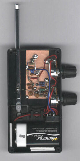
No switch was used in my receiver. Instead, a stereo 3.5mm socket was used and the third contact used to switch the supply. Note that this trick only works when a mono plug is inserted! I mounted the earphone socket such that it traps the battery in one corner of the case. I expect this apparently cool solution is going to come back to bite me when I drop the radio, and the socket gets smashed off by the momentum of the battery!
In operation the regeneration control is increased until a rushing sound is heard. This noise indicates that the circuit is oscillating but will diminish when a signal is received. At this time the tuning and regeneration potentiometers can be adjusted for best reception. The receiver will be found to be most sensitive when the regeneration is set so that the circuit is just oscillating.
Purists will add an RF gain stage prior to the regenerative section, as this minimises coupling of oscillations to the antenna as well as adding sensitivity. In practise the circuit is sensitive enough but one should be aware that RF radiation from the antenna can interfere with nearby equipment, in particular, televisions.
If the circuit were operated on a plane it might well interfere with communications so on no account should this circuit be used near an actual plane. In any case, you would rightly be barred from bringing such items on a plane, let alone be permitted to use one!!!