Regenerative Multi-Band Receiver
FM Transmitter (and stereo version)
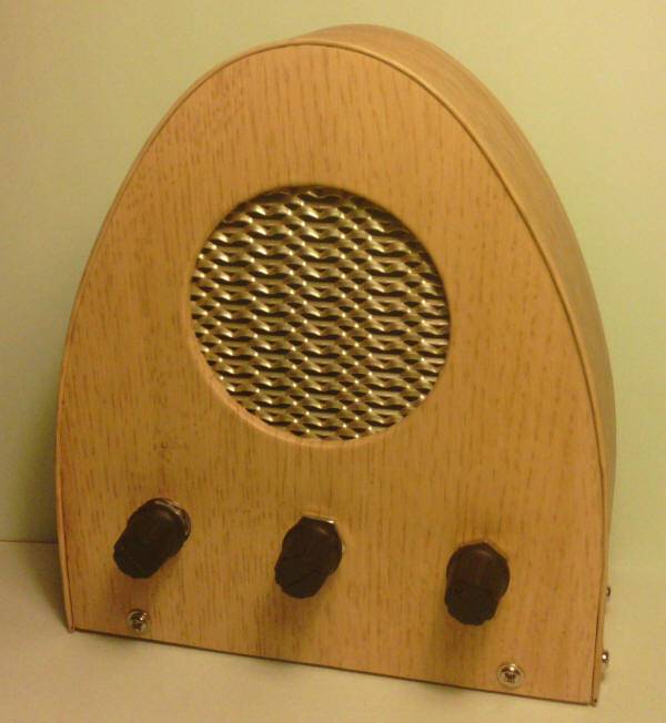
I thought you might be interested in a little novelty radio I've made that is based on your regenerative receiver design. With some component changes I could make your circuit work down to long wave frequencies. With a three position switch I was able to make a long wave / medium wave novelty radio that resembles what we call a cathedral radio. The standard inductor values given in the circuit cover most of these bands. A simple audio amplifier provides quiet loudspeaker volume (an enclosed case helps tremendously here). It was something of a battle to keep the whole thing stable! I suspect many alternatives to the European transistors will work in this circuit but a substitute for the BC109C should have a highish beta. I was able to pull in all our local stations along with some foreign ones with a twenty foot indoor antenna.
Here is a new slant on the ubiquitous FM transmitter circuit. It's an FM sender. It takes a line-level stereo signal, and puts out a mono FM signal which can be received in another part of the house. It uses base modulation, which has always worked well in the author's experience, though spread in base-collector varicap behaviour may conspire to cause the occasional unusable transistor.
Treble pre-emphasis is included, as required for FM broadcast transmission. There is
hardly any high frequency audio roll-off, however, so there is a theoretically possibility
of 19kHz components of the audio setting off the stereo decoder in the receiver. The
author has never actually witnessed this happen.
All capacitors, with the exception of the two in the audio input section, must be ceramic
for adequate performance at VHF. Components around the VHF section must be gouped closely,
and have short leads. Other components are uncritical. The author used a fixed capacitor
for tuning, though a 5-20pF trimmer could easily be substituted. In the author's case,
tuning was accomplished by opening and closing the turns on the coil. Opening the turns
increases the oscillator frequency, closing them lowers it.
If you aren't sure of your transmitter's frequency, and you have no suitable equipment to
measure it, you can try looking for harmonics on a domestic television with an indoor
aerial. You will probably find two or three, and you can convert the channel numbers to
frequency using the following formula:
f = 387.25 + ( Ch * 6 ) MHz
So, for example, if you find harmonics on channels 24, 41, and 59; then these correspond
to 531.25, 633.25, and 741.25 MHz, and we conclude that the fundamental is at around
106MHz.
This transmitter was designed more for stability than for range, so operates at relatively
low collector current to minimise thermal drift. No antenna is necessary for use
room-to-room. Drawing only around 4mA, this circuit will operate for some 125 hours from a
Duracell battery.
If an antenna is desired, you can add a single turn link coil about five millimetres from
the 'cold' end of the main coil, connected to about a foot of insulated wire. Stability
suffers when you do this, but range is increased to around 100 feet.
A note of caution when operating this transmitter from the mains. Use of a plug-in 'wall'
power supply is recommended for safety. Even then, however, you will probably discover
that the received signal is deluged in hum. Supply line ripple isn't the culprit, as one
might first suspect. It's caused by the switching of the rectifier diodes which present a
varying RF load to the relatively unstable oscillator. For those who are adequately
competent, the power supply can be opened, and 10n 100V ceramic capacitors can be placed
over each diode, effectively shorting out everything at RF. DON'T EVER ATTEMPT THIS ON A
SWITCHING POWER SUPPLY.
Audio line level varies from equipment to equipment. If you experience under- or
over-modulation, you can try driving the circuit from the headphone socket. The volume
control then acts as a 'modulation depth' control. Alternatively, you could try
substituting a potentiometer for the 10k resistor marked *. On no account must the unit be
driven from old valve equipment where voltages can be dangerously high!
Your 'station' will probably sound different to others on the FM dial. Don't despair! The
broadcasters use no end of compression, spectrum tweaking, etc. to make their sound punchy
and appealing. Yours will be truer to the original program!
Remember that use of these transmitters may violate the laws of your country, and that
harmonics might interfere with your neighbour's TV, etc. The onus is entirely on you to
ensure that you are not breaking the law or causing a nuisance.
Happy sending!
Here it is at last - the stereo version of the FM sender:
Output Transformer:
This can in fact be accomplished with a single chip - the BA1404, or the newer NJM2035.
But I say - why do it with one chip when you can use five? :) ( - or four chips, if you
use the dual version of the opamp - the CA3240).
Seriously, this circuit works well as the sender end of a wireless headphone solution, in
conjunction with a personal FM radio. The power is sufficient to service the author's
house, though stereo loss occurs if I venture off down the garden. Alternatively, it can
be used to hear various MP3 players, iPods, etc. on the car radio, where there is rarely a
facility for external input.
The circuit just fitted into a case with integral 9V battery compartment (the sort that
comes with a clip so that you can attach it to your belt, pocket, etc. though I didn't use
this). Externally, the case has just a switch, a short lead to a 3.5mm stereo jack plug,
and a two foot length of aerial cable. A small hole is drilled to allow access to the
tuning trimmer without having to open the case.
All capacitors around the transmitter section must be ceramic. Leads must be kept short
here. A self-supporting coil is used (because it's cheap), but to stop 'twangs' being
transmitted when the case of the unit is bumped, the whole transmitter area, including the
coil, was caked in candle wax. One must, of course, leave the trimmer accessible for
tuning purposes.
If you have the equipment to set this circuit up precisely, then I probably don't need to
explain how to do it! Set-up can be accomplished without any equipment, provided a stereo
signal source is available, and a stereo FM radio with headphones connected (headphones
will enable you to easily hear when stereo sound is being decoded).
The set-up procedure is roughly as follows:
1. Adjust the transmitter section tuning trimmer to place the sender's signal in a an
empty part of the FM dial (if such a space can be found these days!).
2. A good starting point for the Pilot tone level pot is about 30% of setting.
3. Apply power and connect the stereo sound source to the circuit. Set the modulation
level pot to minimum for the moment (i.e. maximum resistance).
4. Listening with the stereo radio, adjust the 76kHz frequency pot until the (albeit
quiet) received signal suddenly resolves into stereo. This may be indicated on the radio
by a 'Stereo' LED illuminating. Ensure that the radio is able to lock and resolve stereo
every time by tuning it to another station momentarily, and then returning it to the
sender's signal. You will find there is a range of settings of the frequency pot over
which stereo can be obtained reliably. When the bounds of this range have been determined,
set the 76kHz frequency pot to the centre of this range.
5. If stereo cannot be obtained at all by these methods, try repeating your efforts after
increasing the Pilot tone level pot a little.
6. Finally, adjust the Modulation level pot so that the received sound has the same
subjective volume as the commercial stations on the dial. It might be best to set the pot
a little lower than this, as commercial FM stations are often subjected to compression so
that they appear louder for a given modulation limit.
The Modulation level pot enables the circuit to be adapted to the particular level on the
'Line out' socket provided of most CD players, etc. If it is intended to connect several
devices at different times, then it may prove necessary to use the headphone socket in
each case, so that the volume control can then be used as a modulation level control
instead.
FM radio employs 'treble pre-emphasis' by which signal frequencies above a certain
frequency are lifted, so as to overcome noise. The 'time constant' emplyed for this
purpose differs from country to country. In the US this time constant is 75us. In the UK
it is 50us. It will be necessary to select an appropriate resistor in the opamp circuits
so that the required pre-emphasis in your country is applied. Suitable values for the UK
and US are given in the circuit.
Do make sure you don't annoy neighbours by jamming their favourite station! These circuits
are not illegal in many countries so long as they do not interfere with legitimate
services. Regardless of their legality, remember that you might just need that neighbour's
help one day, and he may be less inclined to give it if you've ruined his favourite
classical listening!
Finally, the 10mA current drain allows some fifty hours of use from a duracell battery. If
a shorter range can be tolerated (e.g. if the circuit is only ever used in the car where
the circuit can be sited close to the radio aerial), then greater economy can be achieved
by increasing the emitter resistor (1k) in the transmitter circuit.
Happy stereo sending!
The 'Super Stereo' effect of headphone listening is undoubtedly part of the experience for many of us, and adds to the listening enjoyment when listening is all we are doing. But when you just want background music to accompany, say the reading of a book, then the 'in your face' (or more accurately 'in your head') nature of full stereo is an unwanted distraction.
The reality is that pre-recorded music is intended to be used with speakers. Full separation in this case maximises the width of the sound stage and overcomes the inevitable cross-talk that occurs on the sounds' journey from your speakers to your ears (some portable hifi units even employ negative crosstalk to enhance separation on closely spaced speakers).
The problem when listening through headphone arises because infinite stereo separation leads the brain to think that the sounds are originating very close to the ears, or even inside the head! This problem was addressed more than thirty years ago in a hifi magazine, and gave rise to a number of other solutions, based on differing models of the listening environment. Today, with the proliferation of personal hifi equipment, this need is as great as ever.
Essentially, the aim of these early designs (and indeed later ones) was to process the sound so that it appeared to originate from a pair of speakers in an average sized room, say, forty degrees disposed either side of the head centre line. While many sophisticated 'room simulations' have been tried, the substantive requirement was simply to introduce a little crosstalk to narrow the stereo stage slightly.
In addition, however, a major feature of the average domestic listening situation is the complete lack of any directional information in frequencies below around 1kHz. This is because sound vibrations below this frequency tend to diffract around the head, and lead to an almost equal intensity of sound in both ears. This fact is exemplified in '5.1' home theatre systems, which generally only employ a single sub-woofer unit.
The following circuit accomplishes both requirements, introducing crosstalk at high frequencies (above around 1kHz) and producing a near-mono sound below this frequency. The subjective effect of doing this is to remove the sound source away from the listener, i.e. it no longer appears to be coming from very near the head. The circuit is passive in design, allowing it to be built into the smallest of in-line boxes.
This passive solution is not without it's penalties however. Firstly, there is a reduction in listening volume. As a consequence of this, power consumption of the personal hifi is greater (you inevitably set the volume higher to compensate), leading to shorter battery life. Lastly, the processor presents a much lower ohmic load to the hifi than most headphones, which might possibly lead to overload of the headphone driver circuits.
The first drawback is not usually an issue. If you want this kind of listening, then you will probably listen at lower than usual volume in any case. The battery life problem should be offset against the fact that you don't need to replace batteries in the headphone processor itself! And the lower ohmic load appears to be tolerated by most personal hifis. In any case, there are several branded passive speaker systems on the market which present an equally low load.
The author's design took on the form of a headphone extension cable, with a small plastic box on the socket end. If one wished, one could include a multipole switch to permit the unit to be switched out easily. Whatever the chosen implementation, the unit has been found to greatly improve the listening experience when other activities are being performed.
It is particularly welcome when listening to classical music. But of course, it comes right out when I want to hear Groove Armada at full throttle!
Happy listening.
Version 1, the original code.
Version 2 for Windows. This program will remove 50 or 60 Hz line noise (fundamental and harmonics) and features an audio file capture that grabs the last X seconds of audio (user selected) and a volume boost slider. This program may not work in your system due to the way I make API calls but I am currently working on a better approach.
Version 3 for Windows. Similar to Version 2 but without the troublesome API calls. This program may lag a bit, however, and is best used with little interruption from other applications. It is worth a try if your system doesn't like Version 2.
Make sure that:
'Microphone' and 'Line In' are muted in 'Volume Settings'.
In 'Recording Control' (accessed from the Options -> Properties menu) 'Microphone' or 'Line In' will need to be set as the selected recording source, as appropriate.
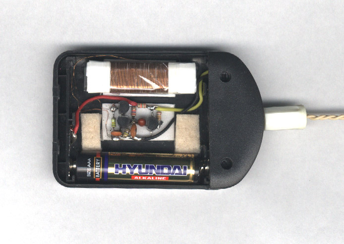
After seeing Charles' new article on matchbox radios, I was thoroughly inspired. I wasn't going to be left out and so here I present my matchbox radio or, more accurately, a radio in a matchbox-size plastic box! The perfect box was found in the supermarket and contained tooth picks of all things. It is not only perfect in size, but is also easily workable - something you can't say of most plastic boxes.
A simple three transistor circuit is chosen more out of nostalgia than anything else - I remember seeing this article in a UK hobby mag all those years ago
(http://www.arar93.dsl.pipex.com/mds975/Content/trfradios04.html
). It works well and brings in our three main domestic UK stations loud and clear, though I should point out that I live only fifteen miles from the Droitwich transmitter that radiates them! I suspect this circuit is perhaps not as sensitive as Charles' regenerative designs.
There are a number of problems to be tackled when building these small radios, not least the bulkiness of the tuning capacitor! Charles' move of using a varicap to overcome this problem is a brilliant one. I chose to stay with the bulky capacitor so as to keep with the spirit of the original 70s article. Having built a couple of radios, I have put together a few notes of my own that might help constructors realise their miniature marvels.
Firstly, some thoughts on salvaging tuning capacitors and loopsticks from 'old' radios. There is something disturbing about the logic of wrecking one radio to create another, but we must accept that there is a higher purpose here! Your prosaic AM radio usually has two windings on the loopstick - a main tuning winding, and a much smaller coupling winding. One end of the main tuning winding is usually connected directly to the RF tuning section of the tuning capacitor, making both easily identifiable. Removing the tuning capacitor and loopstick as a matched pair is obviously attractive because your constructed radio will have nearly identical coverage to the donor radio. If the coupling winding is not needed, it can usually be removed because it is normally wound over the tuning winding. But if you leave it in place, make sure its ends cannot short.
If, as in my case, you find the loopstick winding too bulky, then you can consider 'reverse engineering' your loopstick to rebuild it in a more compact form (the cotton-covered wire used in commercial loopsticks minimises inter-winding capacitance but does tend to make the winding bulge quite a bit). To reverse engineer your loopstick, you will need to remove the turns and count them, and you may find this difficult due to the loopstick being daubed in wax. If the wax needs to be removed, you can try boiling it! The result will probably be unusable, but you should be able to unwind the turns more easily (after it has cooled down!). Rewinding the coil using 30 gauge wire in a single layer will lead to a much more compact loopstick, however, one must accept that in doing this we alter the geometry of the coil, and increase inter-winding capacitance. This will lead to a change in the coverage of your radio.
Note that one of the connections of the tuning capacitor (usually the central ones on each side) is deemed 'chassis'. This connection of the tuning capacitor must be wired to that side of your circuit that is AC coupled to ground. If you don't do this, you may find your hand affects the tuning as it is moved towards the tuning capacitor, especially at the high end of the band.
In the interests of conserving space, we often opt to use a switch built into the headphone socket, and most sockets have a 'break' type switch fitted so that the internal loudspeaker can be switched out of circuit when the headphone is inserted. Sockets fitted with a 'make' switch do exist, but they are bulky. But if you intend to use a mono headphone, one can just use an ordinary switch-less stereo socket. If you insert a mono plug into a stereo socket, you will find that a circuit is made between the 'shaft' connection of the socket and the 'ring' connection, as these are one and the same on a mono plug! If you intend to use low impedance stereo headphones, then you can use the trick of driving both phones in series connection by applying mono signals to the 'tip' and 'ring' connections, leaving the common 'shaft' connection unconnected. This has peculiar phasing for mono reproduction but doesn't seem to affect listening comfort. Of course, switching will then not be possible without an integral 'make' switch in the socket, unless you use the following trick:
The transistor in the supply line is switched on when the stereo headphones are inserted, thus enabling power to the rest of the circuit. The audio drive to the headphones is not compromised by doing this, and the audio drive should not find its way onto the supply rail through the transistor, unless there are some heavy currents flowing!
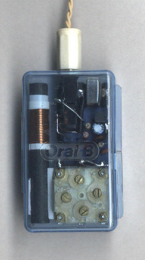
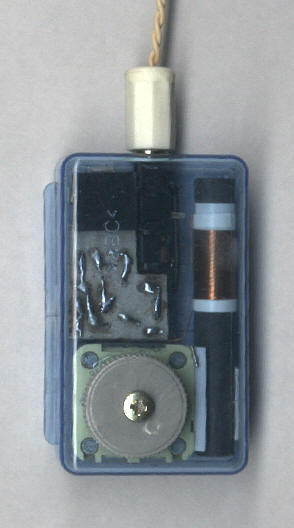
Finally, in contemplating a Long Wave version of my matchbox radio it seemed pointless having a tuning capacitor - here in the UK we have only one domestic service on Long Wave - the Radio 4 service on 198kHz. I decided to make a radio that was fixed in tune to this frequency, and to this end I found that 132 turns on a 40mm loopstick resonated perfectly with a 1000pF capacitor for 198kHz! I actually wound about 160 turns to start with, and then kept removing them until the optimal number of turns were found. One way to tune a radio I suppose! A picture of my fixed tuning Long Wave set is supplied. Note that the case is one of those emergency battery boxes for mobile phones. Note that I placed as much distance between the battery and loopstick as I could, lest the former formed a 'magnetic short circuit'.
The first comment I received on showing someone my radios was ‘it doesn’t have a volume control’. ‘Yes it does!’ I protested. ‘Where?’ I politely took the radio from my partner’s hand and rotated it through ninety degrees! After a short pause he then returned another volley. ‘I can’t do that all the while’ he said dismissingly. ‘Ah, I said, but you have to – AM radios have directional aerials – there’s no getting away from orienting it for best reception. You do that anyway, so why not do it to control volume?’ The alpha male was stumped. For once he didn’t have an annoying but entirely logical answer!