Notoof Remote Telemetry Device - Who needs Bluetooth!
IMPORTANT NOTICE
The circuits on this page are presented strictly for their novelty / educational
/ entertainment value and are not intended to be used in any real world
application. Please read the
DISCLAIMER on the Techlib home page, which applies to all Techlib pages
including this one.
As a hobbyist I use methods and practises I would never use in professional
life. For example, my single transistor RS232/TTL level translator works but it
has absolutely no hysteresis, and in real world applications this circuit will
exhibit significantly higher bit error rate than a purpose designed chip.
The PICs I specify are parts rated for 4MHz, yet I routinely thrash them at
20MHz! I do this because 4MHz parts are cheaper and more easily obtained. In
addition, I haven't yet come across a 4MHz part that didn't run at 20MHz. But no
doubt the day will come!
The point is, such abuses are okay in a hobby setting but sow the seeds of
disaster if carried over to real application. Therefore, none of these circuits
can be considered safe for actual application and, most definitely, MUST NEVER
be used in circumstances where someone's security or safety depends upon one of
them.
This is supposed to be fun!
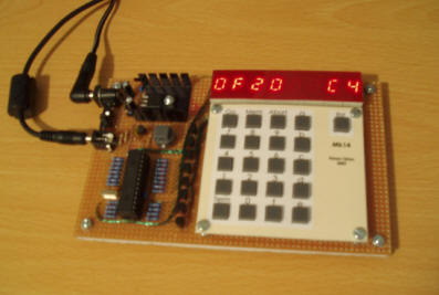
Engineers of my generation in the UK will remember the Science of Cambridge Mk14. Intended to be Sir Clive Sinclair’s first home computer kit for the general public, it served to train a generation of electronics engineers in how to program microprocessors.
The Mk14 was based on, and virtually identical to, the ‘Introkit’ that was available in America at around the same time. It had a 512 byte monitor ROM, 256 bytes of RAM, an eight or nine digit LED display with bubble magnifiers, and a notoriously bad twenty key keyboard.
The Mk14 was the first computer I ever got to program. Most are long gone now and if, like me, you feel a nostalgic desire to relive or repossess one of these venerable machines, then the options a really pretty limited. Basically, you either have to try buying one on Ebay (rare and expensive), searching around obscure component vendors to pull together the parts yourself, or using one of the excellent PC emulators that people have made.
Up until now, if none of those options were acceptable then you were stumped.
The PIC14 is a ‘cycle perfect’ emulation insofar as every SC/MP instruction executes in the same time as it would on a real SC/MP chip. However, the emulation departs in a number of ways from true Mk14 behaviour:
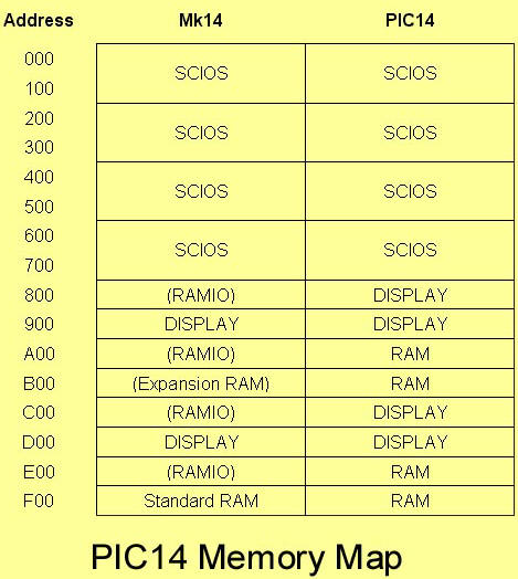
The memory map of the PIC14 is not identical to the Mk14 although it is broadly compatible insofar as the ROM, display and standard RAM are to be found in their correct Mk14 locations. The PIC14 memory map is shown in an associated table which includes the Mk14 memory map alongside for comparison. Note that items not present in the unexpanded Mk14 are shown in brackets (Note also that, although the PIC14 RAM features several times in the memory map, they are just copies – there is only 256 bytes of RAM in total).
Sense A interrupts are not implemented.
SC/MP paging is not implemented. Both program counter increment and pointer arithmetic will carry normally into the top four bits of any address calculation. Mk14 behaviour follows from the fact that these four bits play no part in address decoding. Nonetheless, if a program examines these bits, they may be found to be different to what they would be in an Mk14.
The display column latch is not updated by reads of the display. This aspect of Mk14 behaviour required programs to exercise discipline when scanning the display and keyboard, otherwise ‘ghost’ digits could be generated. This discipline is not needed with the PIC14. Problems can occur with programs that implement column latch update using display read cycles, though the author has never seen such a program.
The emulation is of a 4MHz SC/MP. The Mk14 had a 4.43MHz crystal and clock. In practise this will just cause programs to run 11% slower than they would on an Mk14. Programs that synthesise tones on the flag outputs, for example, would still produce clean tones but they will be around 2 semitones lower in pitch. For those who want a true 4.43MHz emulation, they could try fitting a 22.15MHz crystal to the PIC. This is driving the PIC beyond its specification but might work for some chips. A version of the ‘Alarm Clock’ example found in the Mk14 manual has been produced which is cycle trimmed for a 4MHz SC/MP.
Illegal SC/MP instructions cause a reset. This is actually
an advantage – in the Mk14 a program crash went completely undetected and
often lead to total RAM obliteration.
The emulation is cycle perfect only for programs executing in RAM. ROM
execution runs slightly slower due to approximately an extra cycle overhead
on program fetches from ROM (note however, that data reads from ROM by
programs running in RAM execute at the correct speed). This has connotations
for the use of cassette interface routines provided in some SCIOS monitor
ROMs.
The Mk14 had a characteristic by which the display would sometimes freeze with a single bright digit when the reset button was pressed. Reassuringly, the PIC14 exhibits the same behaviour!
The Mk14 display segment drivers were a bank of AND gates, one input of which was tied to a common line, which itself was tied high through a resistor (one suspects that these gates were present only to protect the preceding make-shift segment latches from the non-TTL levels on the segment lines).
It always struck me as odd that this line wasn’t exploited as a ‘display enable’ signal that could be tied to the SC/MP reset input. This would ensure that the Mk14 display was blanked while the microprocessor was held in reset. There were even a couple of spare gates that could have been used to clean up the relatively slowly changing signal on the reset button. As usual, I suspect time pressure was the reason that this small embellishment failed to get realised.
The PIC14 has a couple of additional features over the Mk14:
The RAM, as programmed through the SCIOS monitor, is non-volatile. This means that programs are retained through power cycles. It also means that a program can be recovered if it overwrites itself.
A serial download facility allows Intel hex files to be sent to the PIC14. This feature is entered automatically following a PIC reset. If this feature is not required, then it can be exited by pressing the SC/MP reset key, in which event the RAM is loaded from non-volatile memory. Files should be transferred at 9600 baud, 8 data bits, 1 stop bit and no parity. As the link is one way, no flow control or handshake should be enabled for file transfer.
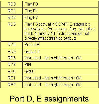
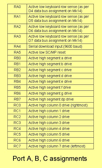
The PIC14 program will run in a PIC16F876, Ports A, B and C providing an interface to the display and keyboard. If the PIC14 program is run in a PIC16F877, then the SC/MP flags can be accessed on the additional Port D and Port E pins. The author is confident that these processor flags and sense lines work, though they have only been tested in simulation, and even then not very thoroughly!
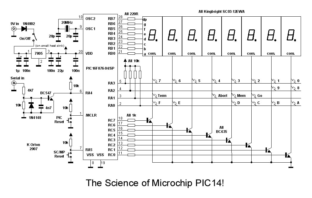
The PIC14 was constructed on square pad board. With the
exception of the power rails, all wiring was point-to-point using enamelled 18
gauge copper wire. A heat sink was fitted to the voltage regulator but is
probably unnecessary. A 78M05 device could certainly be substituted here, though
a 78L05 device is probably optimistic. The ten or so milliamps of segment
current gave a very satisfactory display brightness using the specified
displays. A keypad escutcheon suitable for use with push switch Maplin part no.
FF87U is provided.
Serial connection is through a 2.5mm jack socket that takes a serial lead
intended for a PDA. Be careful if you use a PDA lead – some have strange wiring
and / or resistors built into them. Under consideration is a two chip NIBL
computer using an external RAM chip for program storage. Strictly speaking, of
course, this will be a three chip solution when the RS232 transceivers are
included!
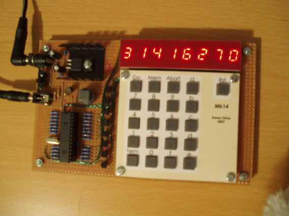
Some would argue you can’t do anything in 256 bytes of RAM. How wrong they are! To show just what is possible, I present my Babbage difference engine emulation! I wrote this partly to demonstrate just what can be done with apparently meagre hardware, but also to provide a test of the emulation, in particular, the decimal addition algorithm.
The Babbage difference engine was remarkable because it accomplished a lot with no more than simple addition. It used the principle of differences to generate high order polynomials. To illustrate how this works, consider the simple situation where we keep adding a constant to a number. We know that the number will keep escalating linearly (e.g. 0, 1, 2, 3, 4…).
Now, suppose the number we add is not a constant, but itself is escalating. The sequence we then produce is 0, 1, 3, 6, 10, 15. This sequence is actually a parabola – a second degree polynomial. By cascading stages of adders in this way, Babbage was able to synthesis polynomials of any order, typically tenth order.
The example Babbage.asm uses tenth order differences but only sixteen digits of precision (only!!!). Babbage knew that resolution at high orders was going to be a problem, and the real difference engines used thirty digits. The example has the engine pre-primed for generation of the function 4.arctan(x) over the interval 0.0..1.0, in fifty steps. If the run is successful, it should finish on the value 4.arctan(1) which is π. Even with just tenth order and sixteen digits, the example arrives at π to within about 11 parts per million!
Happy PIC14ing!
|
|
The message wand is a good PIC introduction as it is a simple
project yet illustrates many aspects of the PIC usage. Used at night, the wand
is swung around above the head, and to onlookers spells out a short message in
the air using flashing LEDs. It could also be used with a handle and spun round
like a traditional soccer rattle (can you still get those?) though great care
must be taken if you do this.
PICs have been popular with hobbyists for several reasons: The development tools
are free, cheap programmers are available, and they come in good old fashioned
DIP packages that you can solder to without a microscope! They are also
extremely versatile of course! The message wand uses a mid-range PIC – the
PIC16F627.
PICs have a wide range of configuration options that are set during programming
(note the ‘__CONFIG’ line in the .asm file). Despite all of these options most
hobby applications don’t need quartz crystal accuracy or access to the chip
reset line. This permits use of the configuration options used in the message
wand, specifically, the options by which all but the power pins are available as
digital I/O!!!
There are some points to watch when using a PIC this way: A
register bit has to be set to ensure the PIC’s internal oscillator runs at about
4MHz (it has a 37kHz option). Another register has to be set to ensure that
certain pins are digital I/O and not analogue inputs. Both of these issues are
addressed by the Message wand.asm file.
Also to bear in mind when applying the PIC16F627 I/O lines: One of the I/O lines
(RA5) is only capable of use as a digital input, while a second (RA4) is only
capable of driving open drain (sounds smelly! i.e. it cannot source current). If
you use any of the other peripherals in the PIC (e.g. the serial interface) then
there are other connotations which have to be dealt with too. But we don’t use
any of those here!
The message wand program illustrates the method of table look-up in a PIC,
specifically, the table that holds the message. This is in the form of pixel
data and can be modified to suit user requirements. Note that no synchronisation
is employed – even though that might be possible. Instead the message is just
repeated at a fixed rate of about three times a second. An eighth pixel LED is
positioned so that it can be seen by the user and arranged to flash mid-message.
When used like a soccer rattle and spun around, it is fairly easy to keep this
flash in one spot thus ensuring that the message stays roughly stationary.
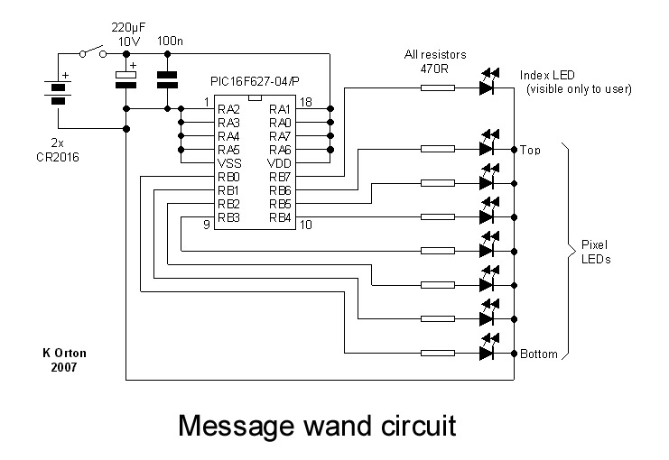
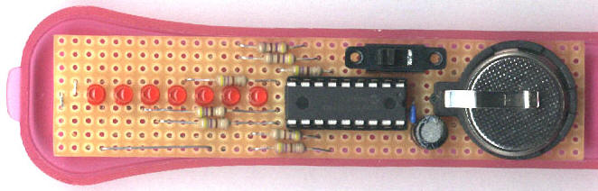
The circuit is simple and can be constructed on plain perforated board. The
circuit is powered from two coin cells type CR2016, both of which were retained
in a battery holder intended for a single CR2032. This is possible provided the
batteries are loaded in reverse, i.e. so that the spring retainer is the –ve
terminal rather than the +ve. Don’t be tempted to omit the electrolytic
capacitor – this is necessary to reduce power fluctuations resulting from
excessive load on the coin cells.
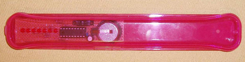
The message wand was built into a toothbrush holder! It is dangerous to swing
around the exposed sharp edges of circuit boards and batteries. An enclosure
with smooth edges is a must and a toothbrush holder provides a reasonably safe
solution in the event of an accident. Even so, it is essential that people are
stood well back when you’re using it. In any case, the message is only
perceptible when viewed from a distance.
Note that I had to nibble away a little of the lip on the lid of the holder in
order that it didn’t jam against the circuit board when closed.
Happy message wanding!
The Orton Orrery is a mechanically scanned planetary motion simulation that uses flashing LEDs in place of the planets. In keeping with 18th century Orrery tradition, only the first six planets (Mercury to Saturn) are present. A single PIC16F627 is all that’s needed to get an Orrery in your living room!
Electrically, the Orrery is two parts: A rotating assembly consisting of LEDs and PIC, and a motor. Both are powered separately – the spinning part draws power from on-board coin cells and the motor draws power from a small plug-in mains power supply. The PIC code includes a phase locked loop (PLL) to maintain synchronisation of the display with motor rotation, thereby avoiding the need for a motor speed controller.
Lunar motion is included in the Orrery - twelve positions of the moon can be displayed. The relative speeds of the planetary bodies are quite closely modelled, though of course size and spacing cannot – unless you happen to have a few acres to spare!
Despite all of the LEDs the duty cycle is very low, and the current consumption of the rotating part is little more than that of the PIC. This means the LEDs and PIC can be satisfactorily powered from coin cells. As these batteries are not intended to deliver much more than a few milliamps an electrolytic capacitor is added to provide a reservoir for the LEDs. While stopped, the coin cells recover and, in truth, exceed the VDD rating of the PIC though this doesn’t seem to be too big a problem.
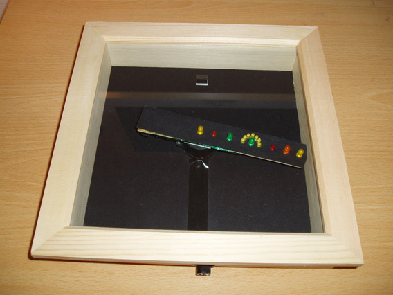
The Orrery was enclosed in a ‘box frame’ as can be bought from craft shops for collage mounting, etc. I obtained a 20cm x 20cm box frame which seemed to be just right. The motor is mounted centrally to the back board of the box frame and a motor power connector fitted to one of the side walls. Cassette motors work best here – small cheap low voltage motors don’t perform well at low speed. My motor was a funny little thing salvaged from a defunct novelty light.
Mounting the assembly onto the motor shaft is easy if you have a metal turning facility, otherwise you have to improvise. Sometimes motors come with a brass pulley which can be soldered to (provided your iron can get hot enough). My motor conveniently had threaded holes which made mounting quite easy. Whatever you do, don’t forego an enclosure – spinning up a board full of LEDs without protection from detaching missiles is simply dangerous – don’t do it!
I have made an observation on human nature when it comes to spinning LEDs: Presented with what appears to be LEDs suspended in mid-air, people cannot resist sticking a finger in, or worse, bringing their eyes up close. This of course is a recipe for a tragic injury so putting the Orrery behind a sheet of glass or plastic is absolutely necessary.
The PLL used in the Orrery is extremely simple yet appears to lock well. A reed switch is used to obtain a rotation reference from a stationary magnet and should lock over the range of motor speeds of about 7 to 13 rotations per second. It is not necessary to scan faster – a perfectly good display can be achieved at just 10 rotations per second.
The PIC Sleep function is used in connection with a time-out on the rotation index, to ensure that the power consumption of the rotating components falls to only a few microamps while the Orrery is not in use.
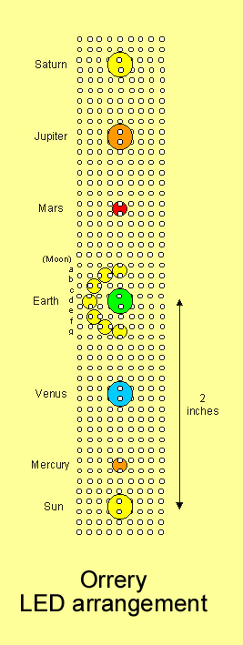
The planet LED placements are uncritical with the single exception of the Sun/Earth/Moon system. These must follow the plan laid out in order for the Moon LED timing to produce a good display.
It is recommended that the rotating part of the Orrery is made using square pad board (pad side down), and that some black card is sandwiched between the board and the LEDs for improved contrast. A further improvement in contrast can be obtained if the back board of the box frame is covered with black card too.
With the exception of the battery, the components can be surface mounted on the under side of the board, the battery being sited close to the motor axis and in opposition to the LEDs to provide counter balance. As with the message wand, two CR2016s are held in a battery holder intended for a single CR2032, the cells being reversed in order that they’re retained within the holder.
The centre of gravity of the whole rotating assembly must lie near the central Sun LED if the thing is not to shake itself to pieces in operation. Again, it is strongly advised that the Orrery is operated inside an enclosure so as to reduce the risk of injury in the event that something does detach and fly off.
Correct balancing of the rotating assembly can be determined by suspending it from a length of cotton, secured to the Sun LED. It should hang perfectly level showing that the centre of gravity is at or near the Sun LED.
Happy Orrerying!
Ever needed to measure a voltage without taking your eye off something? If so, then this is the project for you! The Orton Talking Voltmeter takes a voltage measurement in the range 0-5 Volts and then reads it out to you to two decimal places (i.e. to 10mV resolution). The design illustrates the use of the 10 bit ADC in the PIC, as well as pulse width modulation (PWM) for analogue output. This project also illustrates how to squeeze every last word of program memory out of a PIC! Sound samples consume almost all of the on-chip flash memory, and even that was after some pretty brutal trimming of the samples and a drop in resolution to seven bits. Even after all that, the samples are about as brief as you can get without becoming unrecognisable.

The circuit is so simple it seems almost a crime not to use all of those digital I/Os. The internal ADC of the PIC derives its reference from the supply lines, and to that end a variable voltage regulator is employed to permit full scale calibration. If 5% accuracy is acceptable, then a fixed voltage regulator could be used instead. When calibrating the unit, always set the pot for 5V VDD BEFORE you install the PIC, as the setting may be on the high side to start with. Final adjustment should be done with a known reference attached, which may be nothing more than a battery if a DVM is around to tell you what reference its providing.
The speaker drive shown in this circuit is simple but has a number of drawbacks: Firstly, it is inclined to interfere with nearby radios due to the rapidly switching currents. Secondly, the power consumption is quite high – about equivalent to Class A – and that is too high for battery power to be practical. Lastly, the high level of PWM signal will probably drive your dog nuts! A less minimal but perhaps more conventional approach uses a linear audio amplifier to drive the speaker. If that option is preferred then the output filter supplied with the circuit can be used to obtain a line level signal for the amplifier input.
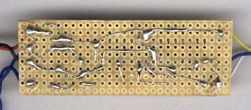
Plain perforated board is ideal for this sort of project (see reverse side photo). Component leads can be easily formed into ‘PCB traces’ with tinned copper wire making up when these won’t reach. Vero pins (can you still get those?) provide anchor points for the leads.
If nothing else, this project has served to remind me how very unpleasant it is to hear your own voice coming back at you like something demented. My best authoritative voice too! Oh no. It just struck me. I sound like my school headmistress.
The Morse beacon can be programmed with a short sentence or phrase, which is then retained in non-volatile memory and subsequently keyed out automatically in a repeating fashion as might be done to advertise a callsign, etc.
The beacon powers up in one of two states, depending on whether it detects a serial lead on its serial port connection. If a serial lead is detected then programming is permitted using a one way connection at 600 baud, 8 data bits, no parity and one stop bit (this rather archaic choice of baud rate being entirely down to the speed of the PIC’s EEPROM!) If no serial lead is detected then the beacon begins keying out its stored message at a rate that can be programmed on a group of switches. An LED provides some indication of beacon state: When in program mode the LED lights continuously, except when data is being received at which time the LED will flicker. When in keying mode, the LED illuminates in sympathy with the keying.
The downloaded message is in the form of a single line of text, terminated with carriage return, line feed or both. Lines of up to 128 characters can be handled (including the carriage return and / or line feed). The downloaded text is interpreted as follows:
A dot ‘.’ causes a ‘dit’ to be keyed.
A dash ‘-‘ causes a ‘dah’ to be keyed.
A space ‘ ‘ causes an inter-letter gap (three ‘dit’s duration).
The sequence ‘ / ‘ (space-slash-space) causes an inter-word gap (seven ‘dit’s duration).
<carriage return> or <line feed> (or both) causes a long gap (25 ‘dit’s duration) and a reset of the text pointer to the start of the message for a repeat.
The rate at which the message is keyed can be set on a bank of four switches attached to the RB0..RB3 inputs of the PIC. The four bit code on these switches sets the speed in the range 5..20 ‘Paris’ standard (the case of all switches ‘off’ selecting the slowest speed).
There are a number of interfacing options for the beacon, outlines for which are provided. A 700Hz square wave is present on the TONE output during keying and this can be combined with the KEY output in the proportions 2:1 to produce an audio signal whose DC level doesn’t shift with keying. This helps to reduce the keying ‘thud’ that would otherwise be heard.
Happy beacons!
This little novelty uses the PIC PWM output to produce an approximation to decaying sine waves, which sound very much better than fixed amplitude square waves, but its still far from precision function generation!! An LDR provides a simple way to detect when the lid of the music box is opened. Alternatively of course, pin 13 (RB7) can be tied low and a microswitch employed on the power rail.
Any box of adequate size could be used. I used a gift box which contained bath crystals etc. but a good alternative is one of those card index boxes. A false bottom can be made for the box to conceal the components, the only visible item being the LDR which can have an unobtrusive presence in one corner.
You might want to include a handle to permit the false bottom to be removed easily. This could be nothing more than a nut, bolt and spacer. A very nice finishing touch would be to line the box and false bottom with felt to give that luxurious feel! Before you do that, don’t forget to drill some holes to let the sound escape from the speaker.
The light sensitivity of the LDR was found to be very adequate, but if operation in near dark is required more sensitivity can be obtained by increasing the 100k resistor. If this resistor is increased too far the logic high level presented to the PIC may be degraded, which would in turn lead to higher current consumption of the PIC while in power down mode.
The tune is my adaptation of a beautiful little song called ‘L’Oiseau’ by Daniel White. Many will remember it as the music to the TV program ‘Belle and Sebastian’ that was broadcast in the UK in the late 1960s and 1970s. The rendition is quite good (if I may say so myself) and might convince some people that it’s a genuine musical box. Other tunes can be substituted provided they fit into 128 note steps and a compass of around 1.5 octaves.
Belle, tu es si belle… the memories are flooding back.
Having bought a cute little ‘paraffin lamp’ from a cut price shop, I decided to make it a little more interesting. Its battery powered of course but its continuous shine and simple on / off ‘wick control’ did not make for anything like a close simulation of the real thing. So, I replaced the on / off control with a variable potentiometer and I added flicker!
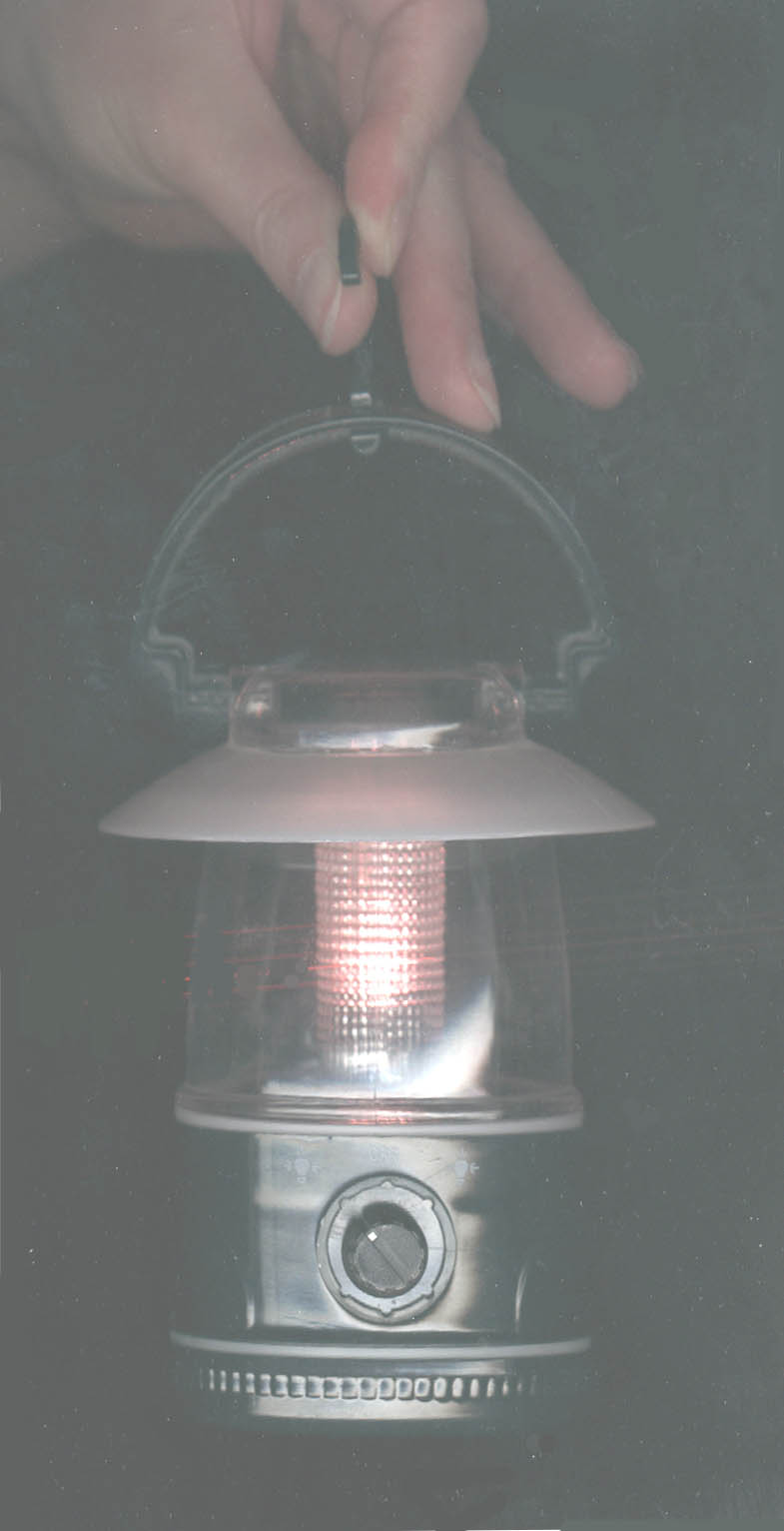
A PIC comparator does most of the work. It is configured as a fairly conventional pulse width modulator to enable the potentiometer to control the bulb brightness. In addition, the PIC uses a pseudo random binary sequence to modulate the bulb intensity and cause it to flicker. The PIC can detect minimum setting of the potentiometer, and implements a low power ‘sentinel’ mode to minimise power consumption when the lamp is turned off. The PIC simply powers up the analogue electronics for a millisecond once every second to see if the lamp has been turned on again. Use of the PIC’s low frequency internal oscillator minimises power consumption while still giving the PIC timing capability. Aren’t PICs wonderful? I dare say this project might transfer to one of the cheaper PIC products thereby avoiding the disturbing situation that the PIC costs more than the rest of the lamp put together!
This project is a portable (i.e. PC-less) hum rejecter (or more accurately, hum estimator) principally for VLF listening application. It employs the PIC’s ADC to sample the hum waveform, and performs a special type of filtering to isolate it. The hum waveform is then reproduced on an external DAC so that it can be subtracted from the VLF signal.
The problem with hum is that it is rarely a single frequency. Switching power supplies, light dimmers and many other appliances conspire to distort the mains waveform so that, by the time it reaches your circuit, it contains many harmonics besides the fundamental line frequency. This makes a simple analogue notch filter ineffective for hum rejection.
The solution is a special filter called a ‘comb’ filter – so called because it has a series of equally spaced notches (or pass bands) that have the appearance of comb teeth when displayed on a linear frequency response plot. This response is ideal for hum rejection because we can arrange that each notch lines up with a harmonic of the mains line frequency, thereby simultaneously suppressing all of its harmonics!!!
The essential component of a comb filter is a pure delay, and in order to work this delay must precisely match the fundamental period of the signal to be filtered. Herein lies the difficulty of analogue implementation – we need a variable delay in the region of 16 to 20 milliseconds. That is difficult to realise in analogue. However, it is not difficult to realise digitally.
One normally wouldn’t consider a PIC for DSP work! Classically, a DSP is distinguished by its ability to multiply the elements of two vectors, element by element, simultaneously summing up all of the products in an accumulator. This ‘multiply / accumulate’ primitive is fundamental to almost all DSP. Most PICs don’t even support multiplication! In saying that, I’ve seen some very impressive DSP feats accomplished with a PIC, including a PID controller and second order band pass filtering for audio.
Fortunately, there are tricks we can use to avoid multiplication completely, provided we compromise on the precise responses of our filters. For instance, the simple first order low pass filter (traditionally implemented as a capacitor and a resistor) is made digitally using a delay element and feedback as shown in the following diagram. In this diagram the gain element α is in the range 0..1 and the time between samples is denoted by T.
Now, if α is restricted to a power of two, then element α can be implemented as shifts alone, enabling us to build our filter from just addition, subtraction and shift operations. A shift of six (α = 2-6) for example, at a sample rate of 8kHz would enable us to implement a first order low pass filter with a cut frequency of 20Hz. This approach is the basis of the adaptation for our comb filter, and is also the means to clean up the hum waveform for phase detection in the PLL responsible for matching the delay to the line period.
The question might arise as to why the PIC can get away without multiplication while my PC-based program can’t. The answer is simply that the PIC can manipulate its sampling frequency to ensure that the mains period corresponds exactly to the digital delay employed in the comb filter. A PC program has no such control, and the main burden of the PC implementation is dealing with an unknown and (in general) non-integer number of samples that form a mains cycle.
I’ve employed this method of using shifts as a substitute for multiplication many times in the past. I once used it to construct a second order band pass filter, but it is rare that you can achieve the desired centre frequency and damping from shifts alone, and so this must be considered the exception rather than the rule. But applied to the first order case, it very often yields a satisfactory solution and permits implementation of many classical DSP functions on microcontrollers and more conventional processors. In this case a low pass filter can be implemented in 40 PIC instruction cycles, or 8μsec at a 20MHz clock.
Samples in the comb filter delay are re-circulated, and a time constant of around one second applied in order to average the hum cycle over many cycles. Noise is not always a bad thing, and in this instance a little noise on top of the PIC’s 10 bit ADC samples permits this averaging to yield a measurement that is significantly more precise than the original samples (those interested in this effect might like to research ‘stochastic resonance’). In fact, we can safely assume around twelve bit resolution for the emerging hum cycle estimate. The main contributor to error is in fact the inevitable jitter of the PLL in its effort to stay locked to the line frequency.
The estimated cycle is reconstructed on a DAC, and then injected anti-phase with the original VLF signal. If scaling is correct the resulting difference should be stripped of hum leaving only the VLF. To ensure that this differencing is successful, the hum estimator (PIC) must impose zero phase shift, and so the ADC / DAC timing has been engineered with this in mind. A corollary to the phase preservation requirement is that any anti-aliasing or reconstruction filtering applied before the ADC or after the DAC should be applied to the VLF also. Happily, it is anticipated that only very light filtering will actually prove necessary in these cases.
In addition to the 50Hz / 60Hz option selection (pin 21) shown in the circuit diagram, there are several other ‘option pins’ that are not shown. These are described fully in the following table.
| Pin number |
Function | HI (left floating) |
LO (tie to GND) |
| 21 | Mains frequency select |
60 Hz | 50 Hz |
| 22 | Output select | Estimated hum (no VLF) |
VLF (no hum)1 |
| 23 | DAC invert | DAC has same sense as input |
DAC is Inverted |
| 24 | PLL filter 1 time constant |
3.5 msec | 7.1 msec |
| 25 | PLL filter 2 time constant |
3.5 msec | 7.1 msec |
| 26 | Hume estimate adaptation enable |
Adaptation enabled |
Adaptation frozen |
| 27 | No function | ||
| 28 | No function | ||
| Notes: 1. Only around 6 bit resolution and 4.5 kHz bandwidth. |
|||
One option permits hum-free VLF to be reproduced directly on the DAC. While this is a minimal solution in terms of components, it is subject to the PIC’s sampling process and so is restricted to an approximately 4.5kHz bandwidth. More seriously, the reconstructed VLF will be rendered to only about six bits resolution. The effect is that it sounds rather less than AM band radio quality, which eliminates those statics that sound like breaking glass. Nonetheless, this might be acceptable in some cases.
Both input and output operate with a DC bias of 2.5V and, due to the ADC and DAC having common references, are amplitude matched quite well. It is likely that the external nulling node need only combine the input and output using precision resistors. It is even possible to invert the DAC output (using pin 23) so that the combination can occur on the same amplifier input!
No coupling capacitors are shown as their polarity depend on the external circuit (though a value of at least 2.2μF can be confidently stated for the input capacitor to the ADC). The 1k resistor on the ADC input gives the PIC some protection from power up transients which might otherwise cause the input protection diodes to conduct, possibly leading to a latch-up state.
This hum rejector circuit has been employed in a magnetic VLF receiver (see below) to very good effect. It does not always entirely eliminate the hum but usually reduces a mind-numbing droning into a sound rather like a bee in the room! Just occasionally a transient causes the PLL to lose lock for a moment, and the hum returns with a ‘DONG!’ like a big ol’ chiming clock! All in all however, comfortable domectic listening is possible with this receiver.
Happy humnulling!
Eager to promote the SC/MP microprocessor as an industrial microcontroller, National released their ‘National Industrial Basic Language’ for this chip. It was quickly seized upon by hobbyists who used it in early home computers. The European publication Elektor ran a particularly popular series of articles on this and other SC/MP projects, and I believe even released programs on 45RPM records!
This project is a three chip NIBL computer with 8 kilobytes of data and program storage. Young ‘uns may scoff, but that was once sixty-four 2102 kilobit memory chips!! I recall a friend who made such a memory by splaying the legs of his ICs and mounting them between two sheets of Vero board, such that the copper strips bussed up all the address lines and power rails. I made him ill by asking him how he will replace a failed part if it happens to be in the centre of this monolithic marvel. Another friend lost.
You talk to the computer using a simple serial link set for 1200 baud, eight data bits, no parity, one stop bit. No hardware handshaking should be selected. The Windows Hyperterminal program can be easily set up to do this, though you may need to acquire a USB-Serial bridge device if your computer is even remotely modern.
NIBL is a fairly typical sixteen bit integer tiny Basic but has a few nice features. I won’t provide an in-depth description of NIBL here, but here are the highlights:
Program elements: IF / THEN GOSUB / RETURN FOR / NEXT DO / UNTIL Bitwise operators: AND OR NOT Variables: A-Z (twenty-six signed sixteen bit integer variables) Special operators: @ (indirection operator – implements peek and poke) # (hexadecimal number entry) $ (string at specified memory address) Pseudo variables: PAGE (current page) TOP (first free address after program) STAT (SC/MP status register) Special statements: LINK (call machine code subroutine)
The PAGE pseudo variable recognizes the SC/MP 4kbyte paging. The program code in each page is treated like a separate program (i.e. line numbers may begin from 1 in each). Moving between these separate program segments is achieved by assigning the PAGE pseudo variable, on which control will be transferred to the first statement on the identified page. Two pages are available in the PICL – PAGE=1 and PAGE=2.
The STAT pseudo variable represents the SC/MP status register and allows access to the flags and sense inputs. For example, the statement STAT=#0F will cause the four flag LEDs to illuminate (as with the PIC14, the IE status bit is brought out as a fourth flag output).
Finally, no speed rating is supplied for the 6264 component as you’ll be hard pressed to find a part that is too slow!
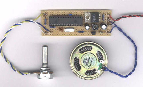
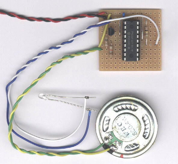
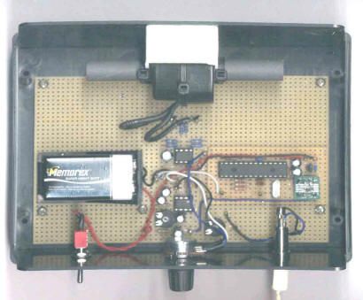
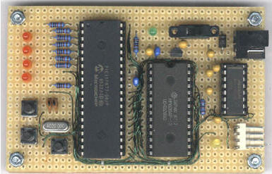
Notoof Remote Telemetry Device
This PIC project permits five analogue signals to be acquired (to ten bits resolution) and transmitted to a remote computer. As well as a conventional serial output, the PIC generates an FSK signal that can be conveyed through almost any audio channel. The FSK output is used in this project to illustrate data transfer using an FM transmitter.
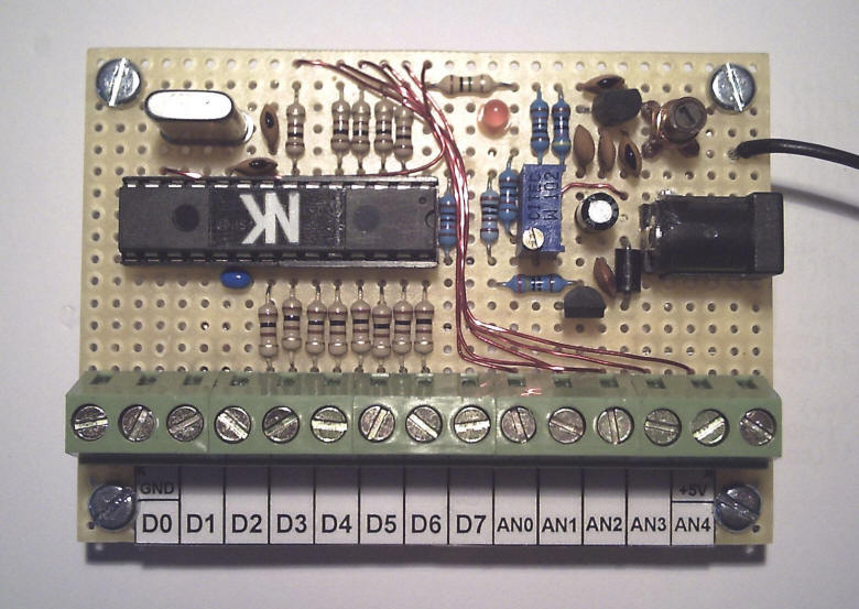
Eight digital inputs are included with the analogues. These have internal pull-up resistors and can be used for recording the state of switches, etc. The serial output is on pin 11 and uses following protocol:
Baud rate: 1200
Data bits: 8
Parity bit: None
Stop bits: 1
The transmission is a line of hexadecimal digits terminated by a carriage return (character 13). The hexadecimal digits are interpreted in pairs (whole bytes) as follows:
Hexadecimal pair Meaning
1 Analog input 0 high byte
2 Analog input 0 low byte
3 Analog input 1 high byte
4 Analog input 1 low byte
5 Analog input 2 high byte
6 Analog input 2 low byte
7 Analog input 3 high byte
8 Analog input 3 low byte
9 Analog input 4 high byte
10 Analog input 4 low byte
11 Digital inputs state
12 Checksum*
* Chosen so that sum of all bytes (hexadecimal pairs) comes to zero.
(Analogue samples are in the range 0..1023)
The FSK output on pin 13 is a digital (two level) signal and uses the following encoding:
A '0' is encoded as two square wave cycles of 2.4kHz
A '1' is encoded as a single square wave cycle of 1.2kHz
Transmission of lines of digits is performed at the approximate rate of four per second, and includes sufficient 'space' time (serial silence) to ensure that a de-synchronised receiver recovers synch. between lines.
The FSK output permits a number of interesting possibilities including cable transmission, radio transmission or recording. Beware in the latter case as compression in digital recorders may distort the waveforms and make decoding impossible. In the past we might have recorded using cassette tape in which case we would have tolerated the occasional 'drop out'.
Whatever method is used, the checksum serves to detect errors that occur in the transmission process so that faulty lines can be discarded. Although the update rate is approximately four samples per second, the real aim was one sample per second, with enough slack to cope with the occasional error.
Analogue signals use the PIC supply as a reference. For this reason, an adjustable voltage regulator is used to permit precise control of the analogue reference. Be sure to adjust the preset resistor for around 5V supply BEFORE you insert PIC otherwise the PIC may be over-voltaged.
A VB program is provided which can decode an FSK signal entered through the sound card 'line in' port. All of the acquisition and decoding is handled in a supplied module, a single function being called to obtain samples of the analogue and digital inputs (it will be found necessary to use the Windows volume/mixer settings to select the 'line in' socket as recording source).
The application obtains a sample once per second and presents the state of the digital inputs on some 'LED's. A chart recorder displays the analogue inputs. This is not a 'polished' application - it lacks many features - and serves only to illustrate use of the supplied function.
The analogue and digital inputs have minimal ESD protection. They should not be 'hot plugged' and should not be driven while no power is applied to the PIC. The PIC should ideally be powered from the circuit it is connected to. It is okay to take a little power from the PIC's voltage regulator, but this must be no more than 20mA.
The transmitter uses a manufactured 100nH inductor. An alternative is around 4¾ self-supporting turns of 0.5mm diameter (24 AWG, 25 SWG) enameled copper wire, winding diameter 5mm and total winding length 2.5mm, air cored. The 10pF capacitor should be replaced with a 22pF trimmer.
A short antenna (a few inches) can be attached to the BC547 collector but be aware that it may be illegal to operate this transmitter with an antenna in your country. It is your responsibility to determine legality and stay within the law!
In fact, these transmitters are illegal in my country and so I could not test the circuit with an antenna. Instead, all testing and subsequent use was done with a coax cable connected directly to an old FM tuner.
Finally, the PIC can be clocked from either a 4MHz crystal or a 4MHz ceramic resonator. In the latter case the 15pF capacitors may need to be raised in value to as high as 68pF.
Happy Notoofing!