This circuit is my variation on Charles’ floating 9V supply. My design uses feedback regulation instead of a zener shunt regulator to stabilize the output against battery voltage and load variations. Replacing the shunt regulator with feedback control makes the supply more efficient for output loads of less than about 500ua. That might be important if the 9V battery must supply maximum current or needs longer operational life.
The additional cost over the original design is the addition of the 4N33, R1, R5 and C4. Other optoisolators should work with adjustments of R5 and R1 as necessary to regulate at 9V.
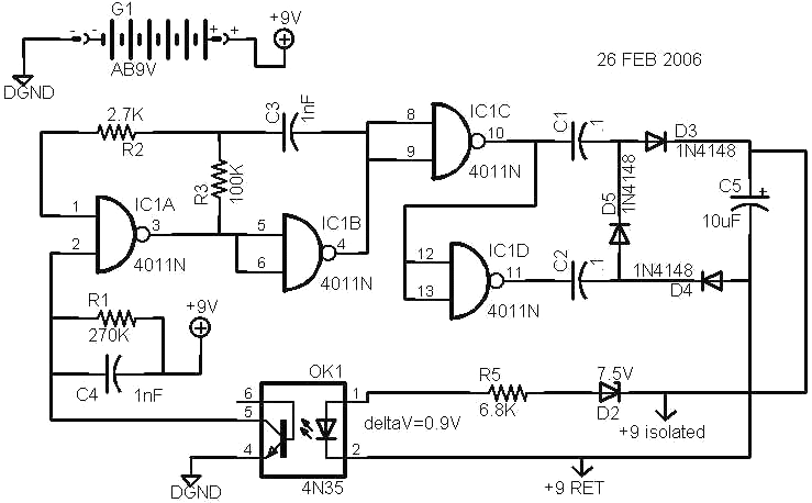
The supply uses switching techniques and a charge pump to generate the isolated voltage and a zener diode as voltage reference in the feedback loop to control the output voltage at about 9V. Here is how it works:
IC1 A,B with R2,3 and C3 form a free running oscillator at a frequency of around 100kHz, controlled by the values of R3 and C3. IC1 C and D are inverting buffers to generate the low impedance, 180 degree shifted square waves needed to drive the charge pump, made up of C1,2 and D3,4,5. C5 is the filter to reduce the ripple in the charge pump output.
Output voltage is controlled by turning the oscillator OFF for periods of time when the voltage at C5 exceeds the desired 9V.
If the output voltage at C5 is below 8.4V ( 7.5V Zener plus .9V LED drop), no current flows in the LED in OK1. No LED current means no light on the phototransistor in OK1 and therefore no current flow from OK1 pin5 to pin4. If no current flows in R1 then the voltage at IC1 pin2 is +9V. Any voltage over about 4.5V is a logic 1 at IC1 pin2 and so the gate is ON and acts like an inverter. This enables the oscillator to run continuously.
As the output voltage rises above 8.4V, current begins to flow in R5 and the LED. When the voltage reaches about 9V, there is enough LED light output to cause the phototransistor to conduct about 17uA of current thru R1. This pulls the voltage at IC1 pin 2 below 4.5V and so turns OFF the oscillator. With the oscillator and charge pump OFF, the C5 voltage drops slightly and IC1 pin2 voltage rises to just over the 4.5V logic threshold and the oscillator starts again and delivers power to C5. Thus the isolated output voltage is held within a small voltage range by gating the oscillator OFF to limit the voltage increase. This regulation works whether the load current or the battery voltage change. At very light loads the ripple voltage frequency on C5 will decrease, since the oscillator is OFF for a much longer time than it is ON.
Output voltage change over the life of the battery ( for a constant load) is much less than the battery voltage change because of the regulating loop.
The isolated output voltage can be adjusted up to about 12V for light loads by increasing the voltage of the zener and/or increasing R5.
Craig Taylor
15 Feb 2007