
Eventually, I'll make this page into a collection of projects but for now it's just a place to start collecting my ideas, much like a lab notebook but with pictures. : )
Precision Thermistors
Notes regarding 0.1 degree interchangeable thermistors (Fenwal, curve 16): Lookup table using LibraOffice: https://www.techlib.com/electronics/thermistor_data.htm. Warn users not to heat the thermistors much past 70C to avoid permanent drift. These are the white ones I have in quantity. Design "ohmmeter" using PicAxe and V/F to directly enter data into a spreadsheet like the Solar Flare project for plotting temperature over time.
RTD Thermometers
Precision RTD simulator with a dual-pole, seven-throw switch (for four-wire resistance measurement). Actually, a four-throw switch with resistors for -50, 0, 50 and 100 would be adequate. I need to analyze the required precision for the resistors for the readers. The reader should borrow, rent or otherwise obtain a very high precision ohmmeter for the job. Mine is a Fluke 8506A. Discuss the various curves. I'm using the "European" curve and the Pico SE012 PT100 probe (alpha = .00385, ITS-90).
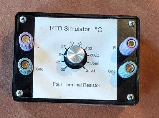
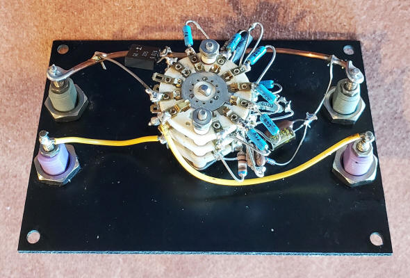
The switches connect the terminals directly to the resistor to avoid any additional resistance due to wires and especially the switch. Lots of time is spent getting the resistors perfect; 0.4% error is about 1degree of error! I was shooting for absurd accuracy, on the order of 0.02%, when I made mine and I think I got closer than that since I matched the published data to as many digits as they offer. But things always drift a little, especially when soldering. I'll call it 0.02% conservatively. Note: it would be better to build the simulator in a metal box with the ground connections connected to the case or, probably better, a ground terminal that can be connected to the ground of the RTD amplifier.
| Pico SE012 Resistance | |
| -50.00 C | 80.31 ohms |
| -25.00 C | 90.19 ohms |
| 0.00 C | 100.00 ohms |
| 25.00 C | 109.73 ohms |
| 50.00 C | 119.40 ohms |
| 75.00 C | 128.99 ohms |
| 100.00 C | 138.51 ohms |
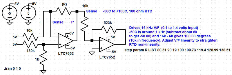
Things are a bit out of order below (I built the dual op-amp circuit below before building the V/F): For the "next step" I built the V/F above but with a few changes: the 1000 pF capacitor is changed to a 3300 pF (3.3 nF) NPO type. The gain and linearity resistors are selected with values ending up near 14.711k and 133k respectively with the 14.711k being the most critical value selected to give an exact 15kHz span from the -50C resistor to the +100C resistor. Only a few iterations were needed since the linearity resistor only impacts the gain slightly. It may be possible that 133k will linearize the RTD without further tweaking - I got linearity beyond the accuracy specs of the RTD; it's certainly a good starting value.
This project is the Killer App for my V/F because the linearity adjustment can virtually eliminate the small natural non-linearity of the RTD. The chart below shows the resistance non-linearity of the above simulator measured with a precision voltmeter using the op-amp circuit below (blue trace). The red curve data was read directly from a frequency counter after tweaking a V/F to exhibit the "proper" cancelling non-linearity. The circuit to the left below converts the RTD resistance into a voltage suitable for the V/F (about 100mV to 1.6 volts). Add a 390pF (that's too small as I re-read this) low-leakage capacitor across the RTD (R) and a 0.1uF polyester cap across the 523k feedback resistor. That resistor is a combination of resistors selected to be near that value. Precision is less important than with the simulator but stable resistors are mandatory. The simulator box is used to calibrate the V/F, both for absolute gain and linearity. The frequency of the V/F was tweaked to give the exact span using the simulator then the offset was noted (I'm leaving the offset alone since it's a trivial matter to subtract an integer, even with a PicAXE). The V/F will output a full-scale frequency near 16 kHz which represents 150C: (16,000 - 1000)/100 = 150.00 giving 0.01C resolution. My setup gives the correct frequencies to about 0.01C over the range of the test box - not bad! To determine the zero value just set the test box to 0C and the offset is that frequency. That offset is for all temperatures.
Note: the Spice circuit below is a bit misleading. There are two "current" lines that connect to two of the RTD connections but the two sense lines connect to the other two RTD connections. There's a connection as indicated but it occurs inside the RTD. I'll figure out a way to clarify that in the future.
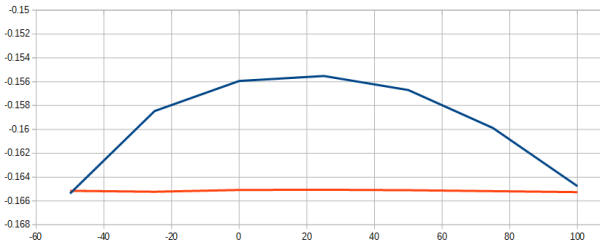
That red curve is "real" data read right off a frequency counter! The blue curve shows the expected non-linearity of a platinum RTD using precise values every 25 degrees. The p-p deviation over the wide range is just under one degree for the uncompensated RTD. I can't really see much error in the red curve. I've always wanted to linearize something with the V/F and now I have. : )
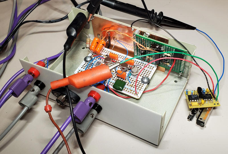
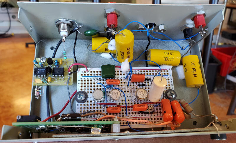
The box contains the RTD amplifier above and a synthetic ground circuit (to allow the circuit to run on a single supply while providing a precise and stable 5 volts). The V/F is off to the right with gain and linearity pots temporarily attached. Note the 4-wire resistance measurement terminals are connected to a mini-Din connector for the commercial RTD but also four Banana jacks for the simulator box or bare-wire RTDs. Those could be 5-way binding posts.
I need to discuss the wiring approach to eliminate ground voltage errors, newer chopper-stabilized op-amps. OPA2388 looks great and is inexpensive but the artificial ground circuit needs to be modified to supply a total of 5 volts since the OPA2388 is a low-voltage part (5.5 VDC max.). Maybe the reference voltage gets dropped to 4 volts.
After tweaking the V/F for the right gain (span) and proper non-linearity (methodically entering the data into the spreadsheet to see the results) the frequency (after subtracting the integer value needed to get exactly 10 kHz at zero C and then dividing by 100) was within 0.01 C of the simulator's value. RTDs aren't really that good, so this electronics won't degrade the best of them. The RTDs don't drift when heated the way thermistors can.
Final unit with V/F installed. The Corning glass capacitor (390 pF) and the large green polyester capacitor were added from the output to negative input of the first and second op-amp respectively (to reduce noise). A 750 ohm resistor is added in series with the V/F output to the BNC connector. I plug in the commercial RTD and I feel like I now know the room temperature to a few hundredths of a degree. : ) This is a ratiometric measurement so the ratiometric V/F is perfect for that reason, too. It seems to be exhibiting little noise...watching... about 0.25Hz p-p or about 2.5 millidegrees using a 10 Hz gate on a frequency counter. There's a little error at the cold end now, maybe 50 millidegrees at -50C, according to my calibrator. Geez, that's good enough!
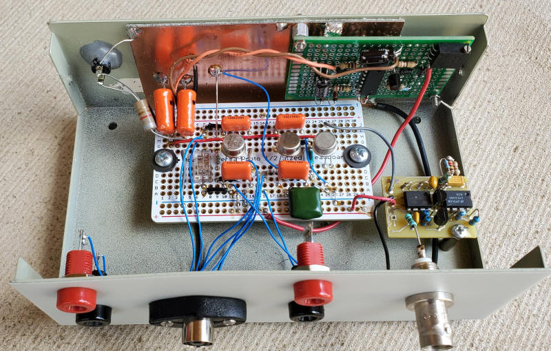
RF interference was capable of changing the readings slightly so I added four 33uH, 2 ohm chokes from the panel connectors to the circuit. I also changed the 390pF glass capacitor to a 4uF polyester type. I also added a 0.22uF polyester cap from the other sense line to ground (BNC lug). These changes eliminated the RF effect.
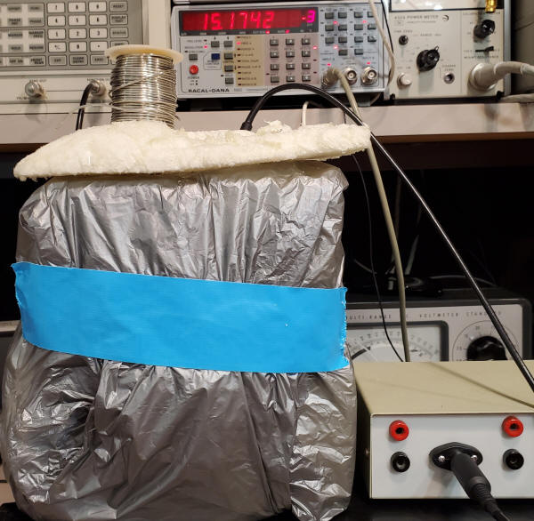
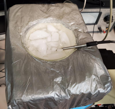
Experiment: Probe in ice water with a Racal Dana 1992 counter doing the math. The indicated temperature is 15 millidegrees. The counter bounces around zero plus and minus a few 10's of millidegrees. I'd say that's good news. By the way, that foam-in-place shipping foam can be removed from the gray plastic and cut into nice shapes like the beaker insulator below. I reused the gray plastic, too. The second picture is the view with the cover removed. I need to buy something to get more foam to make a better cover!
I will discuss thermocouples and the non-linearity problem. It's hard to make a super-precise simulator for the thermocouple so using the V/F non-linearity adjustment to straighten a thermocouple will be more difficult. It's hard to beat an RTD for true precision.
It's also a good idea to add a section covering new semiconductor sensors - they're not shabby. The Analog Devices ADT7422 gets a mention. Maybe my 4-20 mA "process" thermometer at the other house. Discuss using ice water as a cal point and the advantage of having a good mercury thermometer. Did I mention that RTDs are hard to beat?
Silicone resistors! They also have a similar non-linearity that the V/F should be able to vanquish and they're pretty cheap. I have hundreds somewhere. A unijunction transistor is basically a silicon resistor. Calibration would be necessary at two temperatures. The non-linearity tweak could be a fixed value since the ultimate results won't be as spectacular as the high-precision RTD, maybe a few tenths of a degree C.
And my favorite idea: use ordinary light bulbs like the miniature #385 bulb (28 volt). Tungsten makes great RTDs albeit with more non-linearity than platinum but we've got that covered. Again, each bulb would need to be calibrated with an ice bath and maybe a temperature-controlled "hot box" using a precision thermistor controller and a good calibration thermometer. Use four wires to connect the lamp to the circuit, two for the current and two to measure the resulting voltage. Well, maybe two wires are adequate since the precision won't be that great. Hmm, how about connecting a few in series to get the resistance up - they're plenty cheap.
I need to determine whether the V/F non-linearity resistor could be specified on the schematic as opposed to being selected each time. It didn't seem that sensitive. I suppose it's a matter of just how good one wants the thermometer to be.