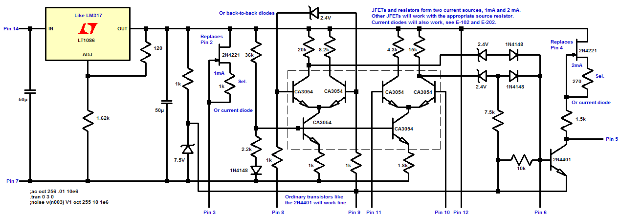

If you have an older power supply with a failed MC1466 regulator IC you have probably discovered how hard it is to find a replacement. After surfing the web for a bit you may have found a pretty spectacular replacement built with extremely tiny SMT parts that isn't much larger than the original IC, an amazing piece of work! You can try to build that but it doesn't look that easy. But many such supplies have plenty of room inside for a discrete version of the IC and there's no reason to stick with the exact schematic; many decisions made in IC design don't necessarily apply to discrete designs. Here's my approach:

The LM317 forms a floating 18 volt regulator, replacing several components. A couple current sources made from JFETs or simply using constant-current diodes replace a few more transistors. The differential amplifiers may be made with discrete components or the venerable CA3054 may be used. You won't see any difference using individual small-signal general-purpose transistors like the 2N4401. The IC just makes the board seem even more clean and simple.
This circuit hasn't been built and tested but here's an LTSpice circuit of a typical regulator made with this circuit. If you attempt this be aware that you might have stability issues to address - it's an untried circuit, except for Spice. If you build this and it works, please let me know!
Notes:
1k resistors may be added to the bases of the second differential amplifier to lower the gain a bit (similar effect of the small resistor in one of the emitters in the original IC design). Protection across the bases could be added. I'd use head-to-head zener diodes around 2.7 to 4.3 volts since the current limit section spends most of its time with a significant differential voltage. The transistors are rated for 5 volts base-to-emitter and adding 0.6 for the other base gives 5.6 volts breakdown rating. The first amp uses a single zener, just to reduce component count by one diode. When regulating the first pair will have very little differential voltage.
Pins 2 and 4 aren't used; the current sources are self-contained in this implementation. The 2N4221 was a convenient choice in LTSpice but many JFETs will work fine with a suitable source resistor. Just select the resistor that gives the desired current. I'd pick a JFET with a reasonable breakdown voltage; some modern parts have a pretty low voltage rating. The current diodes E-102 (1 mA) and E-202 (2 mA) are readily available from the big name online suppliers, much to my surprise. I like the high breakdown voltage of these current diodes (100 volts IIRC).
The 50uF caps on either side of the LM317 are what I was going to use. Those could be 1uF tantalums.