
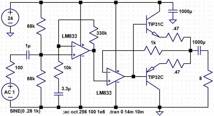
This low-distortion audio amplifier will supply about 5 watts into 8 ohms when configured as shown in the schematic. Power calculates to about 7.5 watts when driving a 6 ohm "satellite" speaker often left over from surround-sound systems. The total distortion measures to be only 0.015% at 1 and 5 kHz using an HP8903B audio analyzer. (Most people can't detect 0.1% distortion.) The 33k on the input amplifier was bridged with 1.5k for the test to eliminate the first amplifier from the test. With full gain the distortion is a little over 0.03% - still excellent and probably due to the CA3240 op-amp I was using at the time.
The reason it works so well is that the "crossover" occurs very close to zero volts due to the precision of the output op-amps. Note the absence of temperature-compensating diodes; the op-amps control the transistors with precision. Each amp watches the corresponding transistor emitter with the only task for all that gain bandwidth being to make that emitter follow the input voltage exactly. When the input voltage passes through V/2, one op-amp "looses control" of the output at the same instant the other one takes over control. The diodes are crucial to the performance in that they allow each op-amp to retain linear operation during their "off" time; the op-amp output only has to swing a diode drop to retain control of the feedback voltage. There's essentially no quiescent current flowing in the output transistors so the standby current of the amplifier is only what the op-amps draw. With the high-performance Quad LS404 op-amp the total current might be only 2 mA with no audio, not bad for a 5 watt amplifier. All the op-amps should be fast audio types with plenty of output current, especially the ones driving the transistors. I like the RC4560, LS404 or LM833 for the outputs but there are plenty of others that will work. A slow op-amp may exhibit a tendency to oscillate and may show distortion above a few kHz. But, I had pretty good luck with the old LF353. My first op-amp is the old CA3240 and it seems fine in that position but you should probably select an audio type. Since it's a dual I could make the first section a two op-amp amplifier with tone control. The transistors need to be quick like those shown. Substitutes or bad grounding technique may lead to instability. I consider this an "expert" level project; it's not unlikely that you will encounter stability problems. Some speakers may require a "snubber" across the output (perhaps 2.7 ohms in series with 0.1uF from output to ground). I recommend using sockets for the op-amps! Also, if you have a distortion analyzer, try tweaking one of the 0.33 ohm resistors by paralleling a low-value pot. You might be able to find a value to parallel across one of the resistors that improves the distortion even further. I didn't this time but it has worked on earlier projects. My 0.33 ohm resistor is three, 1 ohm resistors in parallel.
Notice how a quad and dual op-amp could make a stereo version. A single op-amp will work but with a little more distortion. Eliminate the two diodes and connect both 22 ohms to the op-amp output and both 1k resistors to the negative input. The crossover exhibits more "wiggle" producing a bit more distortion but it's still reasonably good. This technique yields a good amplifier with only one dual op-amp. Don't try to give the output op-amp any gain for best results. Also see a simpler version with more distortion.
This circuit will work with lower supply voltage but the output swing is limited by the swing of the op-amps since the output stages have no voltage gain. But it makes a nice amplifier for voltages as low as 9 volts and with the LS404 op-amp the power consumption is wonderful.
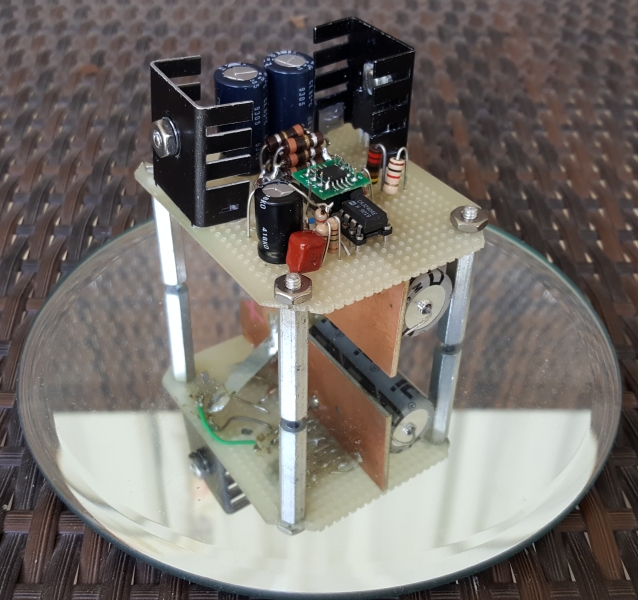
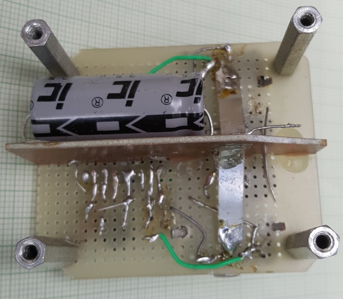
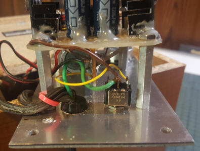
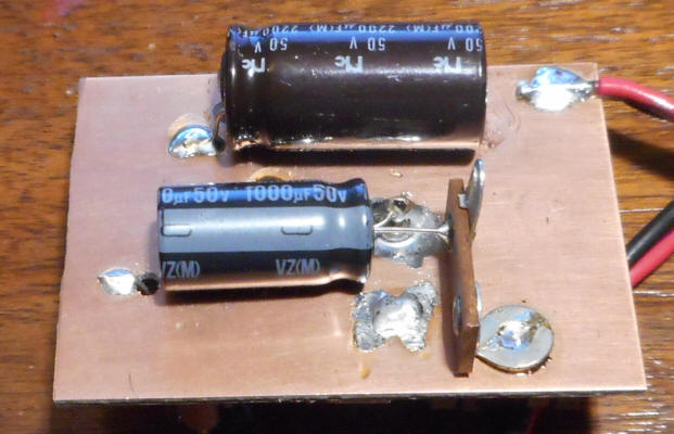
One problem with building projects like this on perfboard is not having low impedance ground and power planes. I solved the problem with a strip of double-sided copper-clad circuit board mounted at right-angles to the perfboard and running right down the middle of the underside. I used a little instant glue to hold it while a couple of globs of epoxy cured. It's also held by a couple of copper strips for the transistor collectors and other wires. (Make the NPN side positive,) Drill a hole for the large capacitor's lead to pass through and use a large drill to "countersink" the hole, thereby removing the copper around the edge of the hole (for insulation).
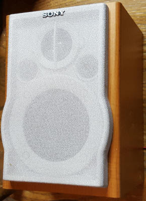
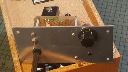
What I do not show is that I've wired a stereo jack to combine both channels of a sound card output. I have two 1k resistors from each output to the input cap. I'm converting a good-quality surplus speaker (a garage sale find) into an amplified speaker for boosting laptop audio:
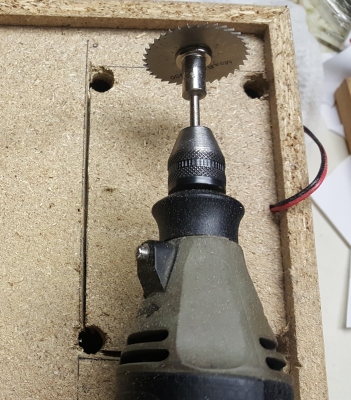
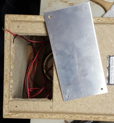
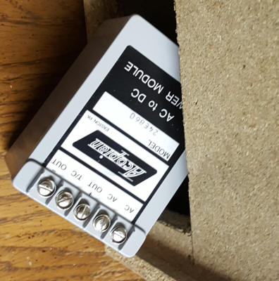
Look what I just discovered! A perfect 24 volt, 600 mA Acopian power supply fits right in the hole I cut. I was going to use an external supply but this is better. I added a switch to either ground or float the power supply.
I love this thing. Keep in mind that this amplifier doesn't have enough power to tax this large speaker but the speaker produces excellent fidelity with the amplifier working within its limits. It's capable of being "annoyingly" loud on a desktop but it wouldn't fill the back yard with music for a party. If you want more power, consider a modern Class-D amplifier. But this circuit would be perfect for speaker amps for a variety of desktop radio or audio projects. It "blows away" my name-brand computer speakers.
If you can settle for more distortion (from about 0.2% to 0.4% at full power) and about 2.5 watts into 8 ohms with a 20 to 24 VDC power supply, the following circuit is a lot simpler. The op-amp has to discharge the base of one transistor to turn it off while also trying to pump charge into the other transistor to turn it on, hence more distortion at crossover. The distortion isn't noticeable for many applications but it's significantly higher than the circuit above. I used a larger, 2200 uF capacitor across the power. If you experience instability try adding a few hundred pF capacitor to the second op-amp from the negative input to the output. This "local" feedback should keep the op-amp happy but it might increase distortion slightly. The circuit will run on lower power supply voltage but at some point you might want to switch to a 4 ohm speaker for more volume. Applications: loud intercom, sound effects, megaphone, signal generator booster, bench amp, etc.
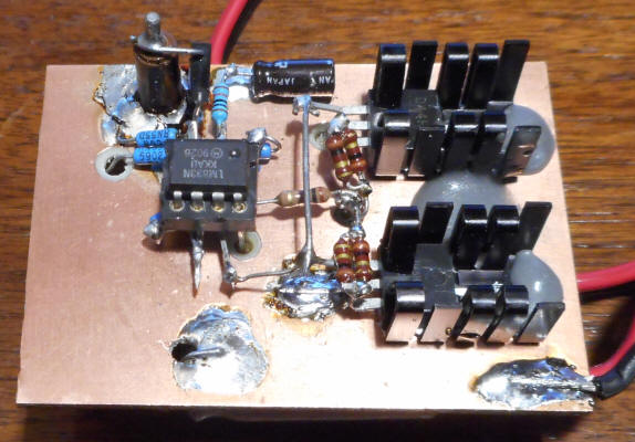
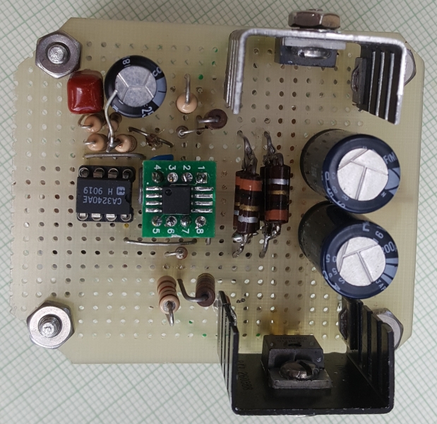
The NPN heat sink has mica underneath since the top layer is ground. The collector lead passes through a hole to the other side which is Vcc. The collector leads hold the transistor on one end and blobs of epoxy hold the heat sink on the other end. The holes that the various leads pass through have countersinks made by hand with a large drill to prevent shorting; you can see a blue resistor top-left in the picture is passing through to Vcc - that's the top 68k bias resistor. Also see pin 8 of the op-amp passing through to Vcc. I used a socket with long "wire-wrap" legs.
Select high gain transistors and quick op-amps that can deliver high output current to achieve the most output power. A limiting factor can be insufficient drive to the transistors for maximum output power. The transistors will be delivering over an amp at the peaks and some op-amps can't deliver as much current near the rails.