
This is a pretty specialized circuit for my particular setup. It is intended for a fairly short whip antenna directly connected to a long coax cable - a less than optimal setup. (I don't want to locate the amplifier at the antenna because I use this antenna for all sorts of purposes.)
I have a two meter whip antenna sticking out of my chimney that I use for a variety of experiments, especially receiving very low frequencies. Until recently the cable was very long and had a capacitance of about 2000 pF. It was nice to be able to stretch the cable all over the basement, but that's a lot of capacitance to have attached to an electrically short antenna. It attenuates LF frequencies by quite a bit. There's sufficient atmospheric noise at audio frequencies and below that a high gain amplifier can make up for the loss. But at LF frequencies above the audio range that much capacitance attenuates the signals too much and one runs into the noise limitations of the electronics.
The first thing I did was cut off most of the cable, reducing the capacitance to about 750 pF. With that reduced capacitance the atmospheric noise on a quiet day at 200 kHz barely rises above the level of a good op-amp. So, it's usable, but just barely. The following project is an attempt to improve the situation so that I can use the antenna to simultaneous receive Schumann resonance at 7 Hz, whistlers and tweaks in the audio spectrum, and "LowFER" transmissions just below 200 kHz. And all this has to be done at the end of the long piece of coax. Here's the experimental circuit so far:
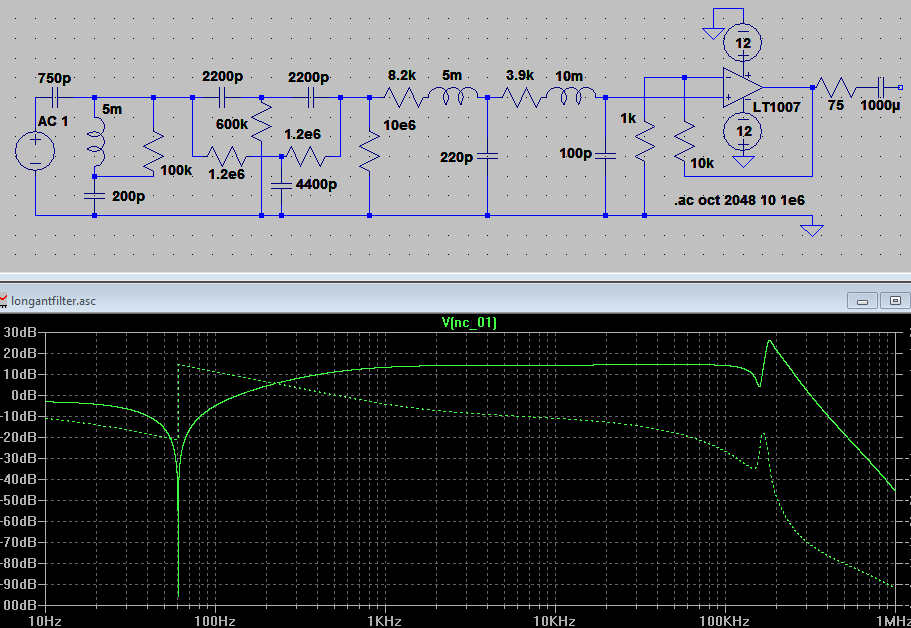
Starting at the left, the 750 pF represents my rather high antenna/cable capacitance. The 5 mH, 100k, and 200 pf resonate with that 750 pF at the desired receive frequency (185.3 kHz in my case). One could just resonate the 750 pF with an inductor to ground but that inductor would "short out" low frequency signals. This tank includes the 200 pF so that the low frequencies are only attenuated slightly and the 100k broadens the resonance a little so that it isn't too fussy to adjust. You can see the response peaking nicely right below 200 kHz. In actual practice you can tune the receiver around to find the peak by listening for the background noise increase. Then tweak the capacitance to move the peak to the desired frequency. The values can be significantly different than those I used in the simulation above. In my current setup I'm using a 2.2 mH, 47k, and 750 pF (try those in LTSpice). That gives a little broader response but I lose a little more signal at the lower frequencies. There's plenty to spare.
Without those three components, the response is flat to 200 kHz then drops like a rock. That flat response is perfectly fine for most reception but you might need every last dB if you are trying to receive LowFER signals. A longer antenna is also a good idea. If more of that capacitance were due to the antenna itself, I wouldn't need to enhance the gain. (But I want to leave this antenna as-is.)
The next six components form a Twin-T notch filter for 60 Hz so that the op-amp doesn't have to contend with a huge audio signal from the line voltage. Those parts should be selected very carefully and can be a series/parallel combination of values to get within better than 1%.
The 5 and 10 mH and the 220 pF and 100 pF form a low-pass filter that dramatically reduces the gain by the bottom of the broadcast band to keep out AM stations. The resistors in series control the Q to give a flat response. Temporarily lower one of those resistors to 1k and run the simulation to see the effect.
If your antenna/cable capacitance is significantly different from 750 pF you will want to change the 220 pF. The simplest way is to use LTSpice. Delete the 5 mH, 100k resistor, and 200 pF to eliminate the resonance but leave my 750 pF. Then observe the voltage on the 220 pF. It should peak a little then roll off just at 200 kHz. Now change the antenna capacitance from 750 pF to reflect your value and change the 220 pF to get the same peaking and roll-off. Look at the output to verify that the response is down only a little at 200 kHz and about 30 dB down at 500 kHz. Add back in the resonating components if they're desired.
Those resonating components may be selected to operate at another frequency. Since they connect right across the input, I use a BNC Tee to connect different networks for enhancing different frequencies. I can remove it entirely for a flat response, too.
The op-amp shown is similar to the OP27 and other low noise op-amps will also work. The output of my op-amp drives a "video" isolation transformer that boasts a bandwidth from <4 Hz to >8 MHz at 75 ohms. I recommend transformer isolating this circuit from other equipment, especially computers. The output cap is huge to pass 7 Hz.
I should point out that this circuit is intended for at least several hundred pF from the antenna and cable. A much lower capacitance antenna/cable setup might need higher reactances in all positions and it would be a good idea to switch to a FET type op-amp. And you don't need the resonating components since your signals will be plenty big. Even with all my capacitance, a few more feet of antenna would bring the atmospheric noise well above the electronics noise.
The gain below 60 Hz is lower than at audio but there's lots of atmospheric noise down there so one doesn't run into the noise limitations of the electronics.
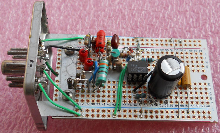
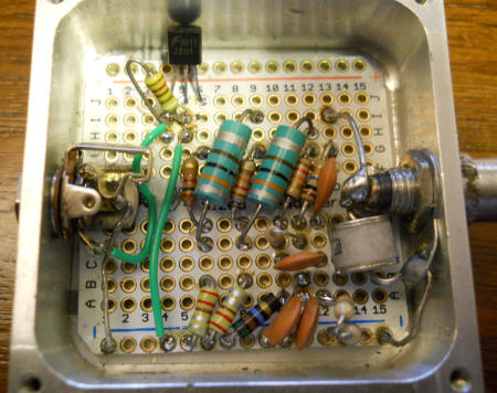
I constructed the circuit on a section of an Adafruit prototyping board mounted on an old-style crystal oscillator header. I seriously doubt that it will even be soldered into a can! You can see several parts stacked in parallel to get precise values for the 60 Hz notch. The 5 mH choke is formed by paralleling two 10 mH chokes. I used an OP37 which is fine as long as the gain is above five (eleven in this case).
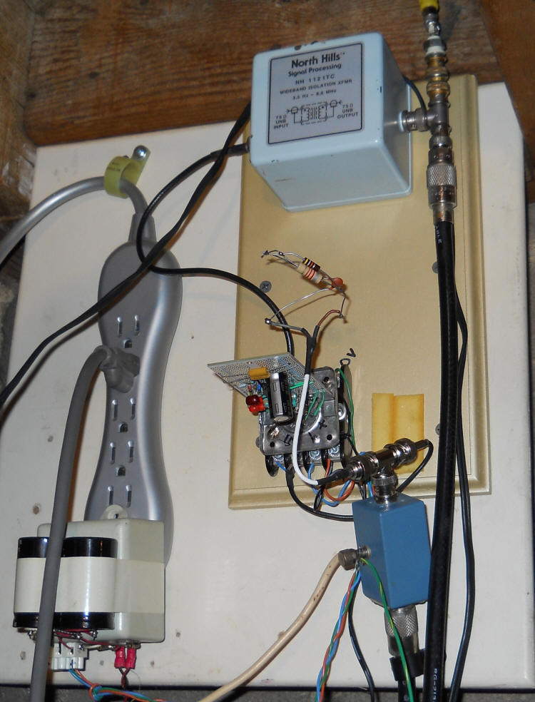
The installation is on a basement wall where the antenna cable comes inside via an old furnace flue. The blue box contains a surge arrestor and is connected to a cold water pipe ground (heavy white wire). The parts floating in the air are the resonating components for 185.3 kHz. I'm currently using a 2.2 mH, 47k, and a 750 pF. The output of the isolation transformer drives two cables going clear across the basement in different directions, one to a selective level meter in a laundry room and the other to my back office. The big blue North Hills isolation transformer breaks noisy ground loops that would occur if the equipment line grounds were directly connected to the antenna ground. The power adapter to the bottom, left provides plus and minus 12 volts, regulated.
The front-end of this design should replace most of my earlier circuits. I built this for a friend and it works as well as the Spice model suggest.
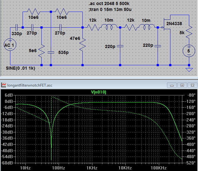
Here's a simple circuit for connecting to a vertical whip or long wire antenna for receiving audio frequency signals (see https://www.techlib.com/electronics/VLFwhistle.htm). The antenna should exhibit about 330 pF of capacitance to ground so add shunt capacitance as needed. The notch frequency may be adjusted slightly by adjusting the 535 pF capacitor so that should consist of a fixed value, perhaps 470 pF and a variable trimmer, say 0 to 100 pF. Adjust the trimmer for the deepest null of the line frequency. The FET may be any of a number of types suitable for microphone amplifiers; I also like the J201. the 5k and 5 volt power source represent the circuitry on a typical soundcard. Just connect the drain of the FET to the tip and ring. The main problem with this approach is that there's no isolation between the receive ground and the usually-noisy computer ground. For those with unlimited funds, there are fiber optic USB extenders that will break the connection but a USB preamplifier (basically a sound card in a box) would be needed at the antenna end. A more economical approach would be to replace the FET with a ground-sensing FET op-amp (the CA3140 is still sold) and use the output of the op-amp to drive an audio "interstage" transformer. The circuit would then run on batteries or a small power adapter.
OK, this has moved on from being virtual:
I made this for a friend and it's every bit as flat as the Spice plot. This needs to replace most of my other front-ends!