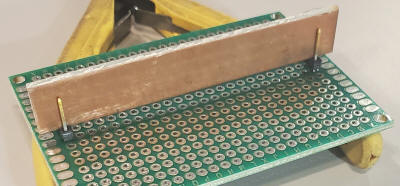
Note: I have not shown any bypass capacitors from 5 volts to ground. Add 0.1uF caps from pin 16 to ground on the ICs. It's a good idea to have a bit of a ground plane, too. I did that underneath with a strip of double-sided PCB material mounted at right-angles to the protoboard, running right down the middle. One side is +5 and the other is ground. It's a pretty handy way to distribute ground and power using those boards. Here's a photo showing the idea before soldering. The two-pin Molex connectors hold the board slightly above the protoboard. It wouldn't hurt to add a bypass capacitor or two across the strip, too.
A few frequency counters and other instruments use 60 Hz as a time base, often generated using a color burst crystal (3.579545 MHz) and a special divider IC. The odd frequency makes it a bit difficult to add an external reference input due to the "3" in 60 Hz; 10 MHz can't be divided by an integer to get 60 Hz. This divider includes a X3 multiplier that selects the 600 kHz harmonic of a 200 kHz pulse and 600 kHz is easily divided to 60 Hz. The input will accommodate a wide range of levels from below -6 dBm to over +18 dBm. The schottky diodes protect the inputs for signals above about 20dBm but they may be left out if the first divider is a 74AC390 due to the robust protection diodes built into the AC logic series or if the reference input won't be inadvertently connected to a powerful signal. You could leave out the diodes and simply use a socket for the first IC for easy repair in the event it somehow gets zapped (unlikely).
The multiplier stage uses the 40/60 duty-cycle output on pin 6 so the voltage averages a bit below 2.5 volts. The 680 ohm resistor to 5 volts pulls that voltage up a bit to center the 600 kHz around 2.5 volts. One could change the order of the divider sections such that the multiplier is tripling a square wave coming from one of the divide-by-two sections. And there's no magic to where I decided to multiply; I just figured a lower frequency might be easier to get working but too low and the inductor and tuning becomes a challenge.
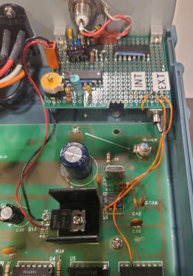
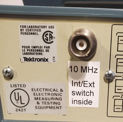
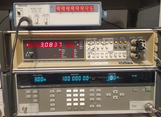
I used this circuit to add an external reference input to a Tektronix CFC250 frequency counter. I borrowed 5 volts right off the regulator IC's terminals and I cut the 60 Hz trace from pin 1 of the MM5369 divider IC (U6) to pin 14 of the CD4017 (U7). Pin 14 is then connected to the center of a double-throw switch. Pin 1 of U6 goes to one side of the switch and the output of my circuit to the other. I chose to put the select switch inside since I'll never use the internal oscillator. It would be more conventional to mount the switch on the back. Note the counter reading when hooked to a synthesized 100 MHz generator. It reads about 5 Hz low at 100 MHz (-5E-8) due to some internal timing limit of around 50 nS. This error is a percentage so it would be only 0.5 Hz at 10 MHz (less than one count in the LSD); it's not an offset error. So it's a very small error, far less than the multi-PPM internal oscillator. To put it in perspective, the internal oscillator drifts 100 times that much during warm-up. It's a nice upgrade for those with an accurate 10 MHz reference.
I'm not going to detail my board. I made so many mistakes and redesigns that the layout is a bit nutty at this point. For example, the multiplier can be seen near the edge of the board, nowhere near the IC to which it is connected under the BNC. But it works!